~4th Gen LT1 F-body Valve Spring Swap~
This is part of a series of articles to aide in the swapping of cam and valve springs on the 4th Gen LT1 F-Body.
As usual, use these instructions at your own risk. I am not liable for any omissions, errors, typos or bad advice. ;-)
Various items that you will need during the spring swap are in this list on my Cam Removal page.

You may already have the necessary parts of the engine exposed if you are also doing a cam swap. However, I will go through the steps in case you are only doing the springs at this time. Some of the info will be redundant from my Cam Removal page.
Remove the negative battery cable (5/16" bolt). Be sure you know the Theftloc code for your radio, if you have one.
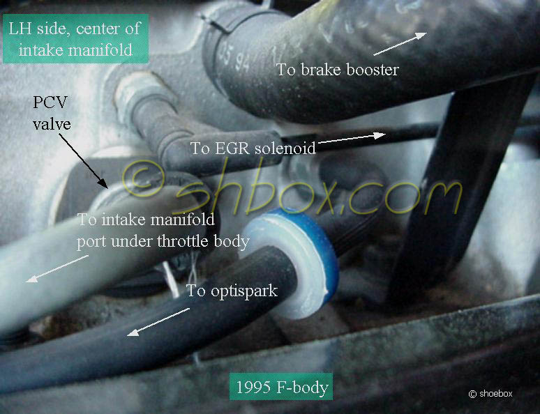
Remove the brake booster vacuum hose from the intake manifold. I then take the free end of the hose and swing it down, out of the way.
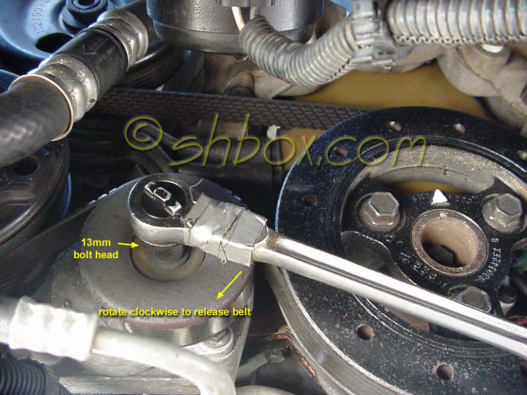
Remove the serpentine belt by releasing the tensioner. A 13mm socket placed on the tensioner pulley bolt and pulled clock-wise will take tension off the belt. You will need to leave yourself room to get your socket and ratchet off, as the tensioner will return farther CCW with the belt off.
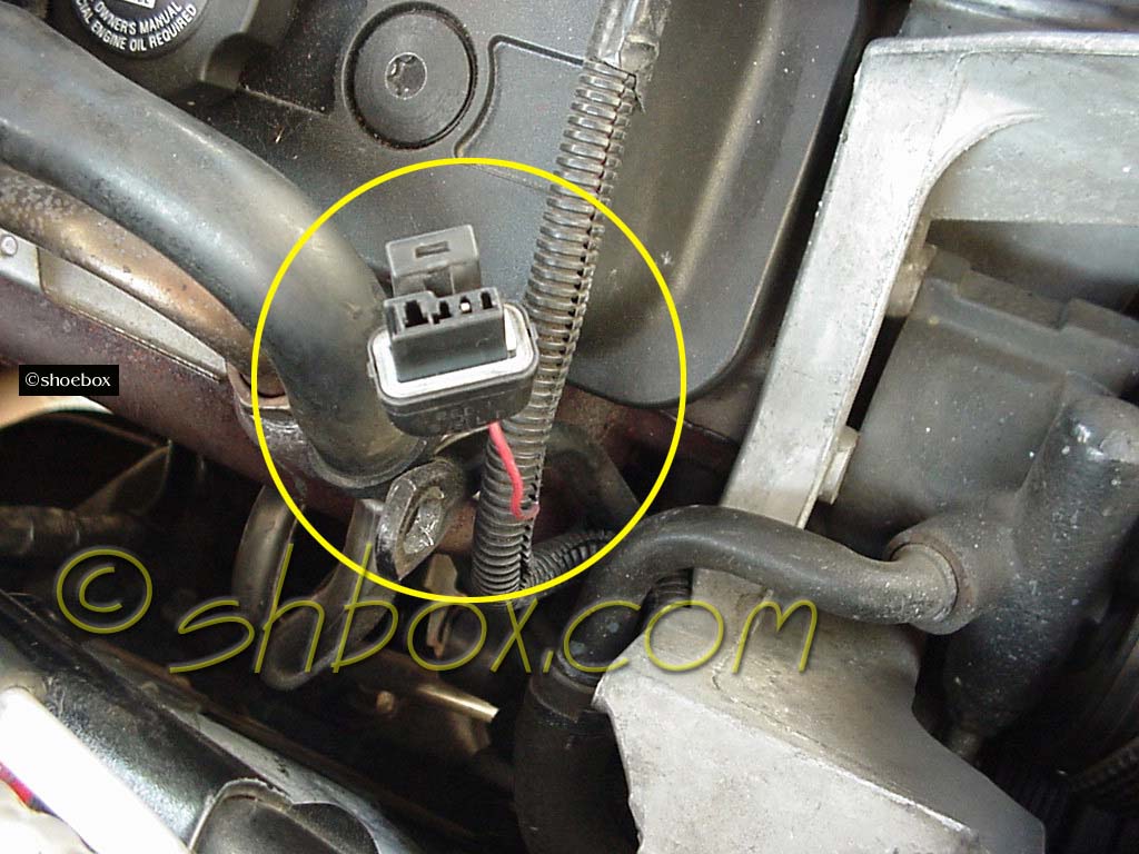
Remove the battery cable to the alternator and remove the alternator. All the bolt heads are 13mm and there is one nut on the long, bottom bolt that is 15mm. Be careful of the small wire attached to the bottom, back of the alternator. It does not have a lot of slack in it. Rotate the alternator up until you can get to the connector and release it.
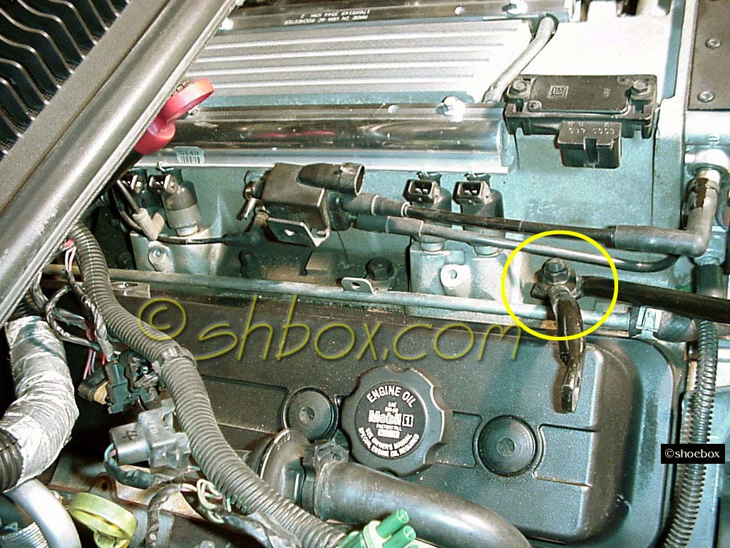
Remove the alternator brackets attached to the RH front intake manifold stud. (9/16" nut)
Some hoses or fuel lines may be in your way. Move whatever you feel you need to.
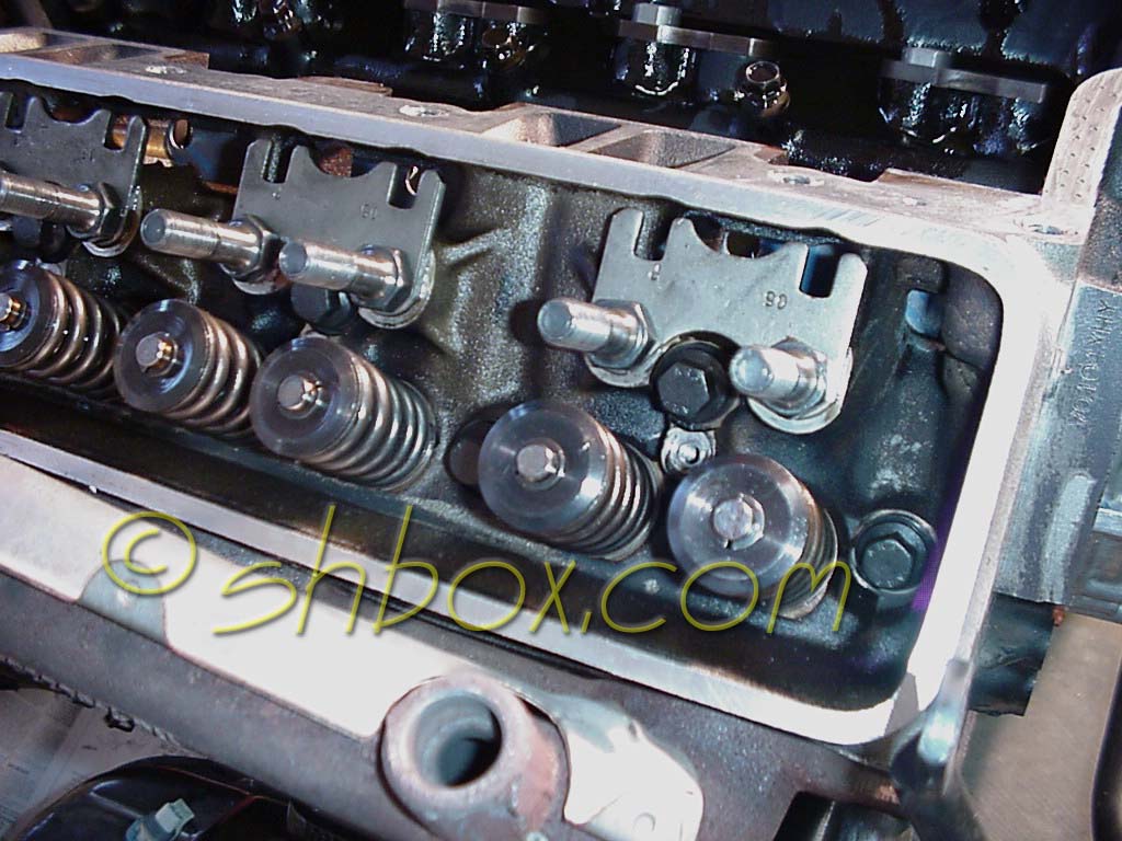
Note this while removing the valvetrain: After you get the valve covers off, observe which valves are open or closed. Manually move the crank pulley until the arrow is at the 12 o'clock position. Look again at the valves, so you can determine which cylinder is at TDC for the power stroke (firing). [The cylinder that is firing will have both valves closed and the one that is on the exhaust stroke will have the exhaust valve open] This will tell you whether you are at #1 or #6 TDC.
If you still have trouble determining which cylinder is at TDC, observe #1 cylinder's valves while someone else turns the crank. When you see the intake valve begin to close, the next time the arrow is at 12 o'clock, the piston will be at TDC. (Obviously, the last thing the cylinder has to do before firing is to take on the air/fuel mixture. That is what it is doing by opening the intake valve. Once it closes, the piston comes up, compresses the mixture and the spark plug fires.)
This info will be helpful to you as you go through the firing order to bring pistons up to TDC for valve spring removal. You can do one cylinder at a time, which may help you tell what cylinder is at TDC.
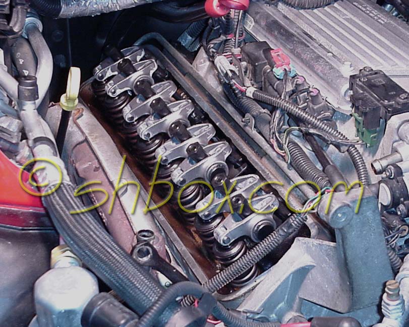
Remove the valvetrain.
There are different methods you can use to keep the valves from falling into the cylinders as you change the springs with the heads on the engine. One, is to use a special spark plug hole fitting and an air compressor to fill the cylinder with air, so that the valves remain closed. Another is to bring the piston up to TDC of the cylinder you are working on. The top of the piston will keep the valve from falling into the cylinder. This is the method I chose, because of the difficultly dealing with the cramped space for the plugs.
Use the arrow on the crank pulley as a guide for determining which cylinder is at TDC. Hopefully, your pulley indicator will be indexed correctly. Note that it could be wrong, because the pulley hub is not keyed and the hub could have spun out of perfect synch. If you have the timing cover off doing other things (like cam swap), you can use the dot on the crank gear as a foolproof way (since it is keyed) of knowing which pistons are at the top of their cylinders. (see following table)
Here is a warning about that, if you can only look at the pulley arrow: when you take your first spring off, the valve seal will usually keep the valve from sinking down. Take a firm grip on the valve stem and push it down until you feel it contact the top of the piston. Be prepared to pull back up on the valve if it does not seem to touch anything (that means don't let go!). This will veryify that you can safely remove the valve seal and the valve will not fall far enough to where you will lose it. If your valve does not find the top of the piston, hang on to the valve (or secure it). Lower it down a little and have someone turn the crank until you can feel contact. Turn the crank, pushing the valve up and find the point where the valve is at it's highest. That will be TDC or real close. Make a new reference mark on your pulley corresponding to the clock position for the cylinder you are working on. That will let you get on with doing the other springs without too much worry.
Because of the nature of the 4-stroke engine, there will always be two pistons at the top of their travel at the same time (one on each bank). If you want, you could swap springs on two cylinders before having to reposition the crank.
|
Crank pulley arrow/crank gear dot position
|
Pistons at top of travel
|
|
12 o'clock
|
1 and 6
|
|
3 o'clock
|
8 and 5
|
|
6 o'clock
|
4 and 7
|
|
9 o'clock
|
3 and 2
|
Now that you have a cylinder ready, the springs can come off.
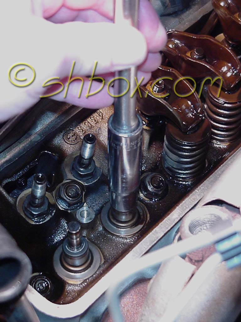
Most times, the valve locks will be a bit sticky. Rap the valve stem or retainer with a mallet or a hammer with socket over the retainer. The shock will normally loosen up the locks, so they will come out when the spring is compressed.
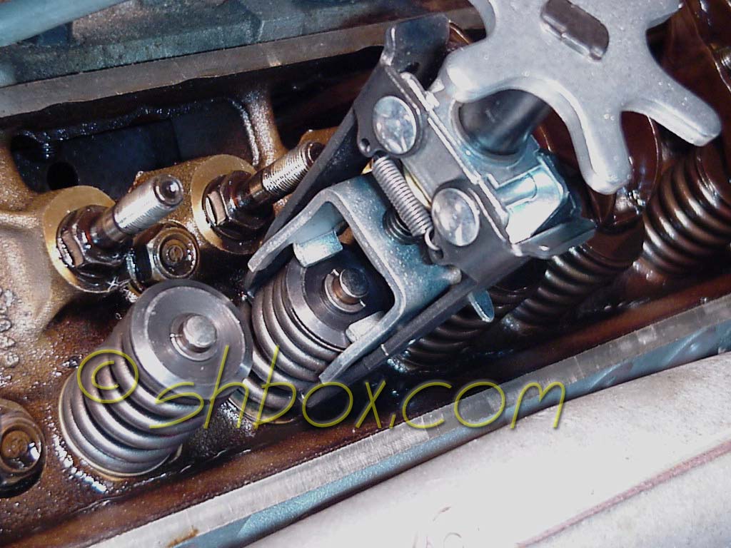
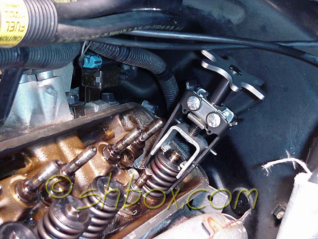
I ended up with this KD tool (2078 - a 3271 is an upgraded version). It is a little hard on the hands, but I wore my Mechanix gloves. There was just enough lip on the tool to grip the flat, inner spring, too. Being careful to center the tool on the spring made a big difference.
I have been told that the Moroso, lever type tool works well. I actually bought a similar design to the Moroso, but it was the Proform brand. I fought with it, because it would not keep the spring straight enough for me to get the new springs back on. Even though the KD tool was hard on the hand, it at least would work. I did find that KD has another version of this tool that has a cover that goes over the crank knob and that the knob can be removed and a ratchet used to turn it. That would be helpful.
If you are installing dual springs, most compressors like the KD, will not grip a round inner spring. You will likely have to use a lever type tool as mentioned above.
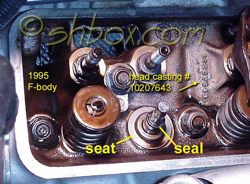
After assembling the tool on the spring, crank it down. Have your magnetic retrieval tool handy to grab the valve locks as they come free. I would not even think of doing this without the magnetic tool. You may have to rock and spin the locks a little to get them out. Once the locks are removed, pull the spring straight up. You should be left with the seal still on and the spring seat under it.
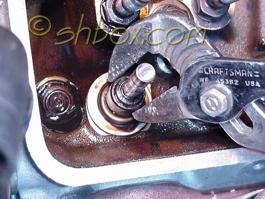
It makes good sense to replace the valve seals as preventive maintenance while you have it apart. Use a pliers to grab the seal and wiggle it up and off. I actually changed to a regular pliers after finding the channel lock type harder to use for this purpose.
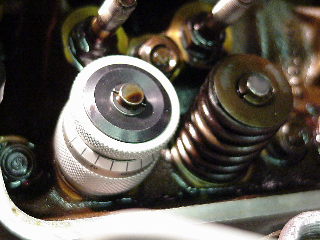
Now is when you can check what the installed height of the springs will be. Clean up the spring base and the removable spring seat. Put the seat back on. If you use a valve spring height micrometer, assemble as shown with your new retainer and locks. Make sure that you pull up on the retainer to lock it in as best as you can. Be sure that your retainer sits on the very top of the micrometer, so your measurements will be true. Screw the micrometer out and take the reading from the side. Get the recommended height values for the spring pressure you need from your manufacturer or seller. Use shims if you need them to get the correct height.
These springs were close enough on the stock heads, that I did not need any shims.
After determining shims, you can put on the new valve stem seal (make sure you have the spring seat installed, first!). They merely slip on and snug over the outside of the valve guide. You can use a small amount of oil to lubricate the seal and valve stem. I did not have one, but there is a thin sleeve that you can get to slip over the valve stem. It will protect the seal as it is slipped on. I used a socket and extension to give it a little tap to be sure it was down all the way. It did not take much.
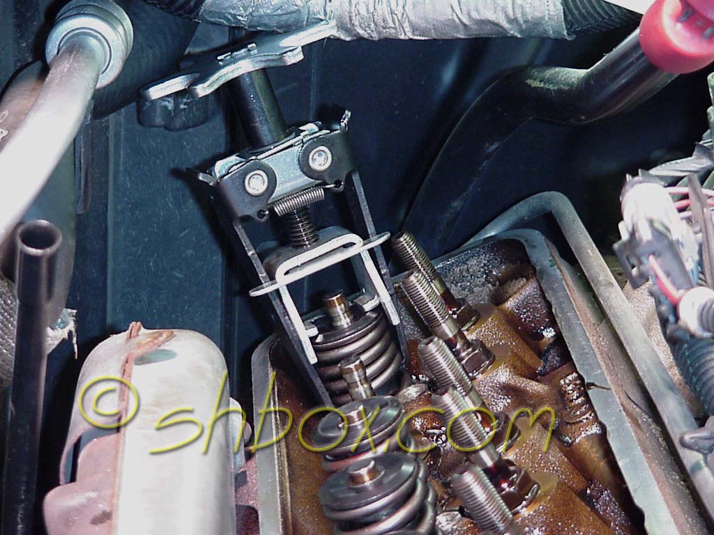
Center your new spring on the compressor and tighten it up. Pull up on the valve stem, so that it is fully up. Your valve seal should hold it up.
Slip the new spring/retainer over the valve stem. Look to see if you have enough room to put the locks on. Carefully put the locks on, one at a time. Have your magnetic tool ready to assist if needed. You don't want to drop any locks somewhere they don't need to go! If it makes you nervous, put rags or towels any place that will help.
Once the locks are in, pull up on the spring/retainer/compressor. This will keep the locks from going anywhere as you release the tension on the compressor. It will also let you make sure you have the locks properly in place. Notice that this and the last pic show that there is enough room to use the KD tool, even at the very back.
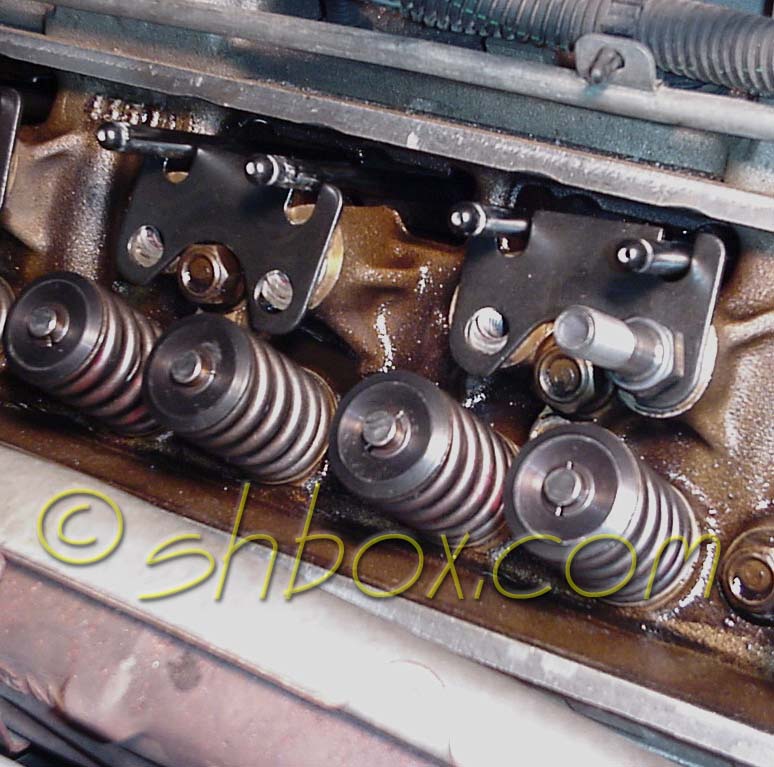
When you get through with the springs, you can add your new studs and guideplates, if applicable. I ended up swapping to GM guideplate p/n 14011051, because they aligned the rockers better. Note that occasionally some random GM guideplates have been found to be unhardened. You can drag a file across a inconsequential edge of the plate to check them. The file should not "bite" in. The Trick Flow TFS 30400623-8 are another alternative people say work well. Other common SBC type guideplates (including Comp Cams) don't seem to have the right spacing for the LT1 (which is slightly different). You can always use an adjustable guideplate such as Isky and others offer. They are a little more finicky to get placed just right.
Remove the old studs with breaker bar and deep six point socket. Clean the holes if needed. Use some red threadlocker or sealant (sometimes a ported head can open up the bottom of the stud hole into the intake runner) on the new studs and torque them to 50 lb. ft. Stock studs are 3/8" diameter on the top side. All studs are 7/16" diameter on the end that screws into the head. The heavier duty 7/16" studs are the same diameter (though different thread pitch) top and bottom, so you don't need any machine work to go with the larger studs.
Be sure to match any new rockers, studs and guidplates you buy as to the stud diameter. I installed new 7/16" studs and Comp Cams Pro Magnum rocker arms to match. The head holes for the studs are heli-coiled at the factory. If you are replacing studs, make sure that the length that goes into the head is not too long. You don't want to bottom out the stud in the head. This can happen if you get studs that are meant to be used with guideplates and then the guideplates are not used.
The threads on the head side of stock studs are pretty short. I would not recommend using the stock studs with guideplates.
Replacing/installing pushrods is as easy as it looks. If you need to check for bent pushrods, roll them on a piece of glass. Blow or look through them for any suspected blockage. Stock pushrod length is 7.200". Guideplate usage makes hardened pushrods necessary. Rather than relying on knowledge that "so and so years have hardened pushrods and so and so years don't", I just bought a new set of hardened ones to be sure. For stability reasons, the stiffer the pushrods, the better (especially if you have an agressive cam).
Pushrod length should be checked if you have any machine work done to the head or block surface. Proper valvetrain geometry is important to maintain. A good article on geometry can be found here.
You should have no problem if you are putting the stock rockers back on. If you are changing to something like the CC Pro Magnums, as I did, you want to make sure that you put the trunion on right side up. There is a machined portion on one side that accepts the poly-lock. If you put it on upside down the nut will sit higher and may touch the stock valve cover. The CC Pro Magnums need for the stock valve cover to be altered slightly to clear. I ended up with LT4 composite valve covers that have plenty of internal clearance.
Once you have all the rockers on, it's just a matter of adjusting them.
It would be a good idea to squirt some oil on any of your newly installed parts, so they won't be too dry on startup.
Install valve covers. (3/8" bolts - torque to 106 lb. in.)
Install/connect alternator and serpentine belt. Bolts that thread into the mounting bracket torque to 37 lb. ft. Torque upper brace mounting nuts to 24 lb. ft. and the lower brace nut to 18 lb. ft.
Your new springs should be broken in with several heat and cool cycles.
edited 3/18/2016
Use any info from this site at your own risk.
You may link to these pages/images but not copy for the purpose of
re-hosting,
reselling or publishing without expressed permission.
Picture or text links to auction sites (ex. Ebay) are forbidden.
All rights reserved by shbox.com.