Programming procedure:
- Turn ignition switch to OFF position.
- Remove RADIO fuse 17 from fuse block.
- Cycle ignition switch from OFF to RUN three times within five seconds until the door locks and the hatch release cycle, indicating the Body Control Module is in the Programming Mode.
- Press and hold BOTH LOCK and UNLOCK buttons on remote control door lock transmitter for 16 seconds.
- Door locks will cycle once, confirming the transmitter code is programmed. The door locks must cycle completely to unlock before proceeding.
- Any transmitter code that was previously programmed has been erased.
- Body Control Module is now programmed to remote control door lock transmitter.
- When programming the Body Control Module to match remote control door lock transmitters, the first transmitter code matched will be stored in memory unless a second remote control door lock transmitter is matched at the same time. If programming the Body Control Module to match a second transmitter, repeat step 4. This must be done before the RADIO fuse 17 is reinstalled.
- Ignition switch to OFF.
- Reinstall RADIO fuse 17 to fuse block.
NOTE:
Always program both transmitters when replacing a lost or damaged transmitter. The first transmitter code programmed will always be in both memories until a second transmitter is programmed within the same sequence.

1995 R.A.P. (Retained Accessory Power) Functions
|
Action
|
Normal Results
|
- Ignition "OFF".
- Open either LH or RH door.
|
- Power Door Locks, Hatch Release and Power Mirrors all operate as long as a door is open.
- Radio and Power Windows do not operate.
|
|
|
- Power Door Locks, Hatch Release and Power Mirrors all continue to operate for approximately 35 seconds.
- Radio and Power Windows do not operate.
|
- Ignition Switch to "ACCY" or "RUN".
|
- Power Door Locks, Hatch Release and Power Mirrors all operate as long as the Ignition Switch is in "ACCY or "RUN".
- Radio and Power Windows operate as long as the Ignition Switch is in "ACCY or "RUN".
|
- Ignition Switch to "OFF".
|
- Power Door Locks, Hatch Release and Power Mirrors all operate for approximately 10 minutes.
- Radio and Power Windows operate for approximately 10 minutes.
|
- Ignition Switch to "RUN".
- Ignition Switch to "OFF".
- Open either RH or LH door.
|
- Power Door Locks, Hatch Release and Power Mirrors all operate as long as a door is open.
- Radio and Power Windows are disabled immediately when a door is opened.
|
|
|
- Power Door Locks, Hatch Release and Power Mirrors all continue to operate for approximately 35 seconds.
- Radio and Power Windows do not operate.
|
1996-1997 BCM Code Retrieval
The BCM can display a series of DTCs, when it is placed in the diagnostic mode. These DTCs are displayed as flash codes through the "Security" indicator lamp on the instrument cluster (much like the 1993 and earlier OBD-I codes are flashed on the SES lamp). During normal operation, if the BCM detects a fault on a monitored circuit, there will be no flashing or any indication that a fault has occurred, though you might detect a system malfunction. The system faults will be recorded as "Current" or "History". A "Current" DTC means that the condition was present when the diagnostic mode was entered. A "History" DTC means the condition has occurred since the BCM was installed in the vehicle, but may not be present currently. If a "Current" DTC is present, the associated "History" DTC will always be present. When you work on systems associated with the BCM, you should always check for DTCs.
Diagnostics is entered by performing the following steps:
- Put the key into the ignition switch and turn it to the RUN position (to disarm the theft deterrent system if equipped).
- Turn the ignition switch to the OFF position.
- Remove the radio fuse from the instrument panel (I/P) fuse block. (1996, fuse 17)
- Turn the ignition switch to the ACC position (enters "Program" mode for feature customization, 1 or 2 chimes for mode verification).
- Within 5 seconds, turn the ignition switch to OFF then back to ACC position (enters diagnostic mode, 3 chimes for mode verification).
The BCM will begin to flash DTCs 4 seconds after entering the diagnostic mode, from the programming mode. Each flash of the "Security" indicator lamp on the I/P represents a number. For example, one flash followed by two quick flashes represents a code 12. Each code is displayed 3 times before the next code is displayed. Any DTCs present are displayed in numerical order. Once the last code is displayed, the list begins over again with the first code. The display continues until the diagnostic mode is exited.
History DTCs are those indicating that the BCM previously detected a fault which later disappeared. Any DTC that has a 3 as its first digit is a History DTC. The reason could be that the fault is a true intermittent only happening occasionally or that the system which the DTC monitors is not currently being operated.
If a visual physical check does not find the cause of the concern, the vehicle can be driven with a DVM connected to the suspected circuit. An abnormal voltage or resistance reading when the concern occurs indicates the concern may be in that circuit.
"Current" DTCs (21-25) will remain stored and display as long as the BCM detects the fault criteria. "History" DTCs (31-35) can be cleared by pressing the door lock switch for a period of 4 seconds while the BCM is in the diagnostic mode. The chime will sound 3 times at the end of the 4 second period as a confirmation that the DTC(s) have cleared.
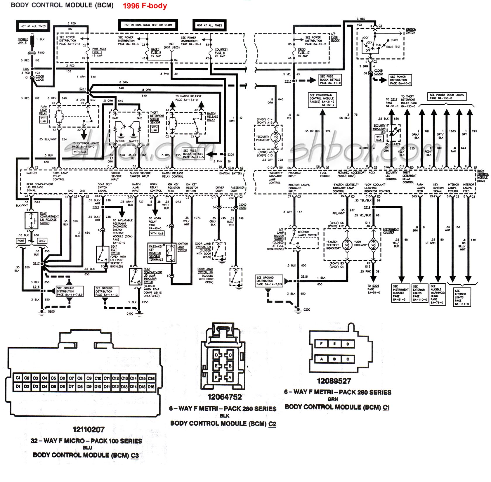
BCM Schematic for 1996 (1997 probably the same).
|
BCM DTC
|
DESCRIPTION
|
|
12
|
Begin Diagnostic Display
|
|
21/31
|
Courtesy Lamps Feed (Circuit Shorted to Ground)
|
|
22/32
|
Courtesy Lamps Return (Circuit Shorted to Battery +)
|
|
23/33
|
Retained Accesory Power (Circuit Shorted to Ground or Battery +)
|
|
24/34
|
Fasten Seatbelt Indicator Lamp (Circuit Shorted to Ground or Battery +)
|
|
25/35
|
Security LED present (with AU6 only)
|
|
41
|
Last Transmitter Message Received Valid (with AU0 only)
|
|
42
|
Last Transmitter Message Received had Invalid ID (with AU0 only)
|
|
43
|
Last Transmitter Message Received had Sumcheck Error (with AU0 only)
|
|
44
|
Last Transmitter Message Received had Encryption Error (with AU0 only)
|
|
45
|
Receiver Processing Currently in 20 Second Lockout (with AU0 only)
|
|
55
|
Begin Configuration Display
-## Hardware Configuration
-## Software Configuration
|
Flush and Refill Power Steering System
Flush procedure:
- Raise vehicle so that front wheels are off the ground and free to turn.
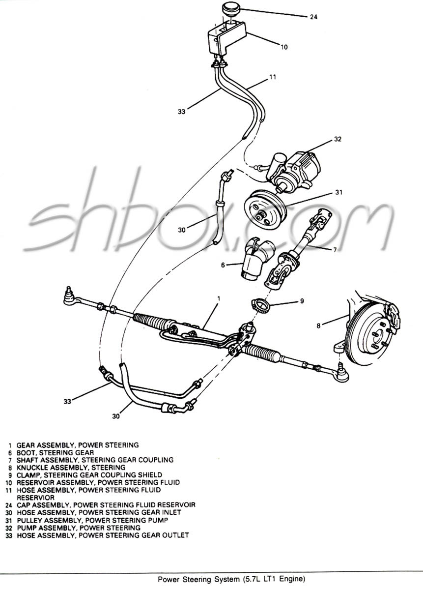
- Remove steering gear outlet hose (should be the hose that goes from the rack to the reservoir #33) at fluid reservoir and plug the reservoir port . You may want to unmount the reservoir to make it easier to get to the hoses.
- Position the steering gear outlet hose (the one you just took off) toward a container to catch fluid.
- While an assistant is filling fluid reservoir, start and run engine at idle.
- Turn steering from lock to lock but do NOT hold it against the stops.
- Continue draining until all old fluid is cleared from system. About a quart of fluid is needed to flush the system.
- Unplug the port on the reservoir and reconnect reservoir hose.
- Turn engine off and fill reservoir to the "C" mark on the level indicator.
- Complete by following with bleeding procedure.
Bleed procedure:
- Ignition off
- Raise front wheels off the ground
- Turn wheel full left
- Fill reservoir to full cold and leave cap off
- With assistant checking fluid level, turn wheel lock to lock at least 20 times. Engine remains off.
- Check fluid while turning for signs of bubbles. If bubbles are seen check for any loose connections.
- Start engine. With engine idling, maintain fluid level. Reinstall cap.
- Return wheels to center and lower wheels to ground.
- Keep engine running for 2 minutes
- Turn wheels in both directions and verify that it is smooth, quiet, fluid at proper level, no leaks or bubbles.
edited 10/10/2004
Testing the ECT (Engine
Temperature) Sensors and Connections
ECT Temperature vs. Resistance Values
|
ºC
|
ºF
|
Ohms
|
|
100
|
212
|
177
|
|
90
|
194
|
241
|
|
80
|
176
|
332
|
|
70
|
158
|
467
|
|
60
|
140
|
667
|
|
50
|
122
|
973
|
|
45
|
113
|
1188
|
|
40
|
104
|
1459
|
|
35
|
95
|
1802
|
|
30
|
86
|
2238
|
|
25
|
77
|
2796
|
|
20
|
68
|
3520
|
|
15
|
59
|
4450
|
|
10
|
50
|
5670
|
|
5
|
41
|
7280
|
|
0
|
32
|
9420
|
|
-5
|
23
|
12300
|
|
-10
|
14
|
16180
|
|
-15
|
5
|
21450
|
|
-20
|
-4
|
28680
|
|
-30
|
-22
|
52700
|
|
-40
|
-40
|
100700
|
Use a Digital Volt Meter (DVM) set to ohms to measure resistance. Note: Use a high impedance meter (at least 10 megohm) when dealing with the PCM. Most modern DVMs will do, but your old analog meter can damage the PCM. It is also a good idea to get a " reference" from the meter you are working with. With the DVM on the ohms scale, touch the two meter leads together and note the ohm reading. It may not always be perfectly zero, but may be within a tenth or two. Now when you take an ohm reading, you will know what the meter will show when there is really no resistance.
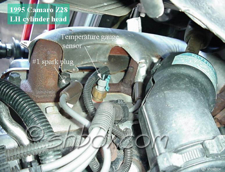
- The sensor in the head has only one terminal. This sensor is for the temperature indicator on the dashboard. Place one test lead on the sensor terminal and the other on a known good ground. Compare the reading to the table. If your car is cold from sitting overnight, the reading should be close to ambient temperature.
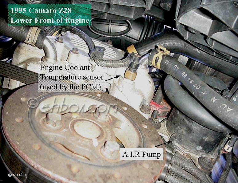
- The sensor in the water pump has two terminals. This sensor is for the temperature input to the PCM. Place a test lead on each of the sensor terminals to take the reading. (When reading resistance, it does not matter which lead goes to which terminal)
If the sensor seems to be ok, you may also need to test at the harness connector for proper lead conditions. Use your test meter set on the dc voltage scale to do this. You will need the key in the RUN position, but don't have to start the car.
- For the one lead connector at the head, place the red test lead on the connector terminal and the black test lead to a known good ground. With the key ON, you should read battery voltage (+12vdc or close to it). You can also ground the lead and see if the gauge in the car deflects to full hot.
- If you get no voltage, switch the meter to ohms to see if the lead is grounded.
- No voltage or no ground mean that the lead is open.
- If the gauge is at full hot all the tme, the lead is grounded back toward the gauge. It could be possible for the lead to be pinched and grounded toward the gauge and broken and open back toward the sensor (like in the case of the wire getting caught somewhere during some major engine work). Physically tracing the wire from the sensor into the harness should locate the problem.
- The two lead connector at the water pump has a black (ground) lead and a PCM +5vdc power lead (probably yellow). Place the black meter test lead to black connector lead and the red meter test lead to the other connector lead (yellow on my 1995). You should read +5vdc because this is monitoring voltage being supplied from the PCM.
- If you get no reading:
- Test the yellow lead by placing the DVM red lead on it and the DVM black lead to ground. A +5vdc reading will indicate the lead is ok.
- If you get no voltage, switch the meter to ohms to see if the lead is grounded.
- No voltage or no ground mean that the lead is open.
- You can test the black connector lead by using the ohms scale on the DVM. Place the DVM black lead to ground. Place the DVM red lead to the black lead of the connector. If the lead is ok, you will get an ohm reading close to zero. If you get no reading or a very high one, the lead is open or partially open.
- OBD-I DTCs 14 and 15 or OBD-II DTCs P0117 and P0118 are typically associated with problems the PCM sees with the sensors or circuits.
Footnote: If you ever have to test the
IAT, it operates the same as the two lead coolant sensor. The same temp vs. resistance table above is applicable to the IAT, as well as the +5vdc lead and ground wire at the harness connector.
edited 1/03/2005
Knock Sensor
The knock sensor system is used for the detection of detonation. The computer retards advance based on the amount of knock received. The knock sensor produces an ac voltage according to the amout of knock. The computer receives the signal and it's programming determines how the computer will change the spark advance.
Diagnostic Trouble Code 43 (OBD-I) or P0332 (OBD-II) can result from a knock sensor circuit or sensor that is faulty. When the DTC is present, the computer will automatically retard timing to protect the engine (since it can no longer sense potentially destructive detonation). Timing can be retarded 10° or more in some driving situations. Performance will be affected.
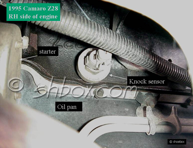
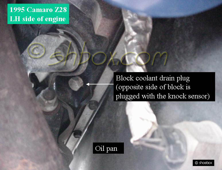
The sensor resides on the RH side (passenger) of the engine block, in the coolant drain location. The F-body uses only one sensor. Other body platforms may use two sensors on their LT1 applications.
On the 1994-1997 LT1 F-body PCM, there is a replaceable module that receives the knock signal. 1993 ECM's have the receiver circuitry built-in to the computer and have no replaceable module.
You may have heard about an LT4 knock module. This module came from the 1996 LT4 Corvette, that had roller rockers as standard equipment. The LT4 module is tuned to allow for the noise the rockers make (not perceiving it as knock). If you have similar valvetrain modifications on your LT1, it may be a good idea to swap to the LT4 module to reduce the chance of "false knock" (knock not related to detonation).
The LT4 module can be used on 1994-1997 engines (OBD-I and II) and no change of the knock sensor is needed (even though the sensors changed in 1996). There is no specific LT4 knock sensor. However, there are differences in the impedance of the sensors between OBD-I and II as listed in the testing section below. You must use the sensor that is matched to your OBD type (or have a wiring modification as frequently done in an OBD type swap situation).
Testing
With the connector off the knock sensor, check for 5v on the harness terminal with key ON. Continue if that is good. If not good, check at pin C8 (1993), D22 (94-97) on back of computer. If voltage is ok at the back of the computer, repair the wire from the computer to the sensor.
Key OFF. Connector off at the knock sensor. Measure the resistance between the KS terminal and ground. Resistance should be between 3300-4500 ohms (OBD-I) or 93k-107k ohms (OBD-II). If it is not, the sensor is faulty or the sensor is not making good contact with the block. Try another resistance reading from the sensor terminal to the outside metal of the sensor body.
If all that is good, it might be a faultly knock module (in case of 94-97) or a problem with the computer, itself.
Knock sensor operation can be monitored with a scanner. Rapping on the RH exhaust manifold or engine block with a hammer should cause the scanner knock value to increment.
OBD-I (1993-1995) knock sensor GM PART # 10456126 ACDelco #213-96
OBD-II (1996-1997) knock sensor GM PART # 10456287 ACDelco #213-325
edited 6/03/2009
Flush the Heater Core
This is the #1 cause for a no heat complaint on a 4th gen f-body.
Remove the heater hoses at the water pump. This allows flushing of the hoses and the core.
Orient the hoses to keep all moisture off the optispark.
Using a garden hose, flush into one heater hose allowing the water to come out the other.
Do not use high pressure. The cooling system is only rated for 18 psi. Full hose pressure can be over 50 psi.
When the water looks clear, swap hoses, flushing into the other one.
Reverse a couple of times to help ensure a good flush.
Re-connect the hoses and refill/bleed the system.
edited 11/05/2008
Coolant Drain and Refill
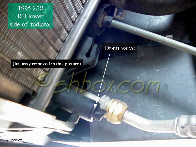
Drain
It is always a good idea to keep coolant away from the distributor (optispark) to avoid any potential problems when doing any of this work.
Refill
- Close radiator drain valve.
- Install block drain plug and knock sensor (if removed during drain procedure).
- If you did the alternate flushing above and have removed the thermostat, you might want to fill the block with your coolant mix through the top of the water pump before placing the thermostat back in. Some people report that this helps to lessen air pockets (I've never done this and never had a problem). Fill until the water pump remains full, install thermostat and water neck, then continue with the next item.
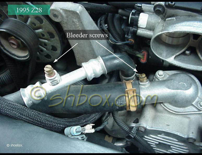
- Using a 50/50 mix of coolant to water, fill the system through the radiator neck (bleeder valves open). You should hear a hiss of air from the bleeder valves as you pour in the coolant.
- LT1 coolant capacities for the 4th gen F-body:
- With Manual Transmission - 15.3 quarts (14.5 L)
- With Automatic Transmission - 15.1 quarts (14.3 L)
- Close bleeder screws when bubbles disappear and only coolant is visible.
- Fill the coolant recovery reservoir to the COLD fill mark. This will provide the extra coolant required to replace the air left in the system upon the first couple of thermocycles.
- Install coolant recovery cap.
- Block wheels and run engine in Park or Neutral with the radiator cap off until thermostat opens (you should see coolant circulating in the radiator tubes).
- With the engine running, add coolant to the radiator until the level is as high as you can get it. This may be tricky if you have an electric pump because coolant may try to gush out-be careful. Install cap sooner if coolant gushes out.
- Install radiator cap.
- Check for leaks after the engine is up to running temperature.
- Monitor engine temperature. If the temperature goes up into the red zone, turn off engine and allow to cool. After it has cooled, check the level in the remote reservoir and correct if necessary. Open the radiator cap and check the level there, too. If it needs much coolant, open the bleed screws as before when filling. Run engine again until the thermostat is open and adjust level as needed. When the system is under pressure (thermostat open, engine running), you can check for air at the bleed screws, if you like.
If, after doing work, you want to verify the coolant level for a few days, check that the level is to the top of the radiator neck when the engine is cold. Add coolant to top it off, if needed. Then, also make sure that the level is correct in the remote reservoir.
Note: It is possible that the LOW COOLANT lamp may come on after this procedure. It should go out after the engine has gone through several heat and cool cycles. Make sure that the remote reservoir is kept at the proper level.
edited 5/23/2013
Cooling System Operation and Testing
Electric cooling fans attached to the radiator keep the LT1 from overheating when there is little or no air passing through the radiator core (car going very slow or stopped and engine running). It is normal for the temps on the gauge to go up to the middle or past middle of the gauge before the fans kick on. The middle of the gauge is in the range of 210º - 220º. With factory programming, the PCM will command low speed fans (or primary fan) "ON" at 226º and "OFF" at 221º and high speed fans (or secondary fan) "ON" at 235º and "OFF" at 230º. The fans should come on before it gets to any part of the red zone. (see "dual fan configuration" below about primary and secondary fans)
The f-body LT1 uses a 180° thermostat as stock. Crusing temps are generally 10°-20° higher than the thermostat rating.
The PCM gets it's temp readings from a sensor that is in the water pump. It uses two wires. If the reading the PCM receives is inaccurate, the fans may not come on at the correct time. The PCM also uses this temperature for lookup in
calculation tables. If there is a problem that causes the reading to be always low (cold), the PCM will add extra fuel. This can cause hard starting when warm and an overly rich condition when running.
The gauge gets it's information from a sensor that is in the driver's side head. It uses one wire. Inaccurate gauge readings can be from this sensor or it's wiring (the wire burned on a header pipe is common). The temp that the PCM sees can be monitored with a scan tool and compared to the gauge reading. They should be close, but don't expect them to be "perfectly" synchronized.
The temperature sensors in the water pump and the cylinder head are not the same. I recommend genuine GM/ACDelco for replacements.
The fans are programmed to come on when the a/c is turned on. A/c Pressure monitoring sensors feed the PCM info and depending on the situation, the PCM may command the fans off for brief periods. If your a/c is broken or operation inhibited because of low refrigerant, the fans will not come on when the a/c is turned on (but will still operate by engine temp). Also, when the car reaches sustained higher speeds, the fans may be commanded off so incoming air can flow through the radiator unimpeded and provide the cooling needed.
Fans will come on when field service mode is initiated and also when the SES lamp comes on. The PCM does this when certain (most) DTCs are detected to protect the engine from a situation where it may overheat.
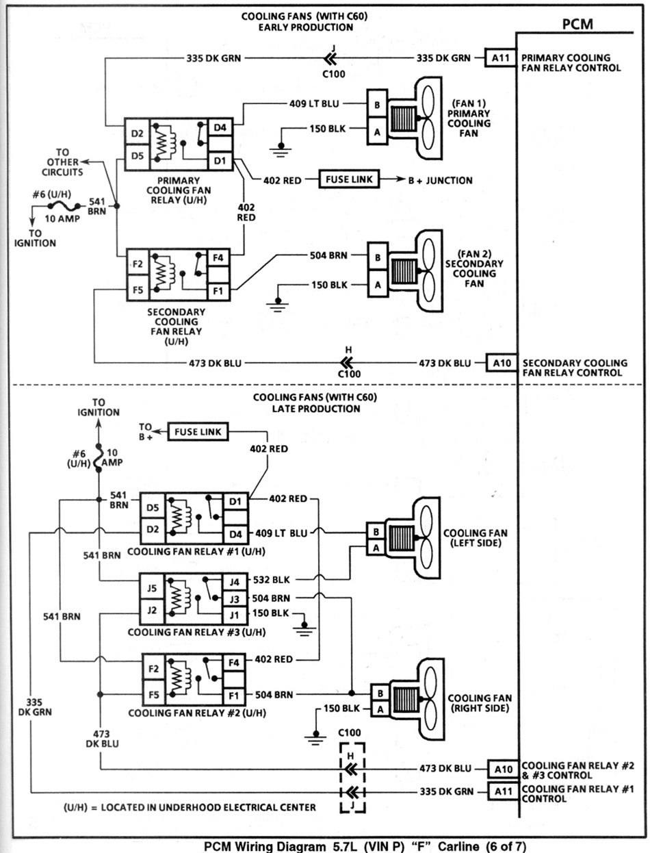
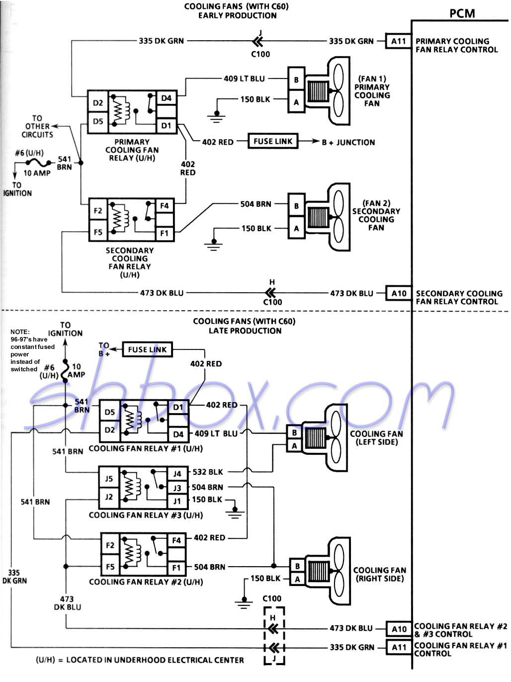
There are two versions of the dual fan configuration:
1993-1994 - Primary and Secondary fans that operate at only one speed. When initially commanded on, only the primary fan (driver side) comes on. It operates alone at full speed. If the temp threshold is met for addtional cooling, the secondary fan (passenger side) also is commanded on. At this point, both fans are running at full speed.
These fans use a two relay architecture that can be seen in the fuse/relay panel that is under the hood.
In late 1994 and into 1995, there was a change to low and high speed fans. When initially commanded on, both fans will come on at a low speed. When the high speed temp threshold is met, they both bump up to high speed. A three relay architecture is used for this fan version (seen in the fuse/relay panel). By adding a third relay, low speed can be achieved by running the power to the fans in series. This way, each fan does not get full voltage and runs at a slower speed. High speed happens when the relays switch to provide full voltage to both fans. Low speed is less noisy and should result in greater fan longevity. High speed is not always needed.
|
2 Relay System
|
PCM Commanded Fan Operation
|
PCM Wire Color Grounded
|
Fan Operation
|
Relay Operated
|
|
#1
|
#2
|
#3
|
|
Primary@226º
|
Drk Grn @A11
|
Primary (LH) fan full speed
|
X
|
-
|
n/a
|
|
Secondary@235º
|
Drk Blu @A10
|
Secondary (RH) fan full speed
|
X
|
X
|
n/a
|
|
3 Relay System
|
Low Speed@226º
|
Drk Grn @A11
|
Low Speed (both fans)
|
X
|
-
|
-
|
|
High Speed@235º
|
Drk Blu @A10
|
High Speed (both fans)
|
X
|
X
|
X
|
|
For both fans to operate in either system, both relay leads must be grounded. Grounding only the Drk Blu wire will result in only the RH fan operating at high speed.
|
Here are some fairly simple things to check for various complaints:
~Fans are not operational at any time~
Check fan fuses in the underhood fuse/relay panel
Check fan relays (same location). Aside from getting out any electrical equipment to test the relay, you can swap it with another one (such as the fog lamp relay) and test for function. See if the relay works for the fog lamps and/or the swapped-in relay makes your fans work. Nearly all the relays in the panel are the same, except for maybe the ABS relay.
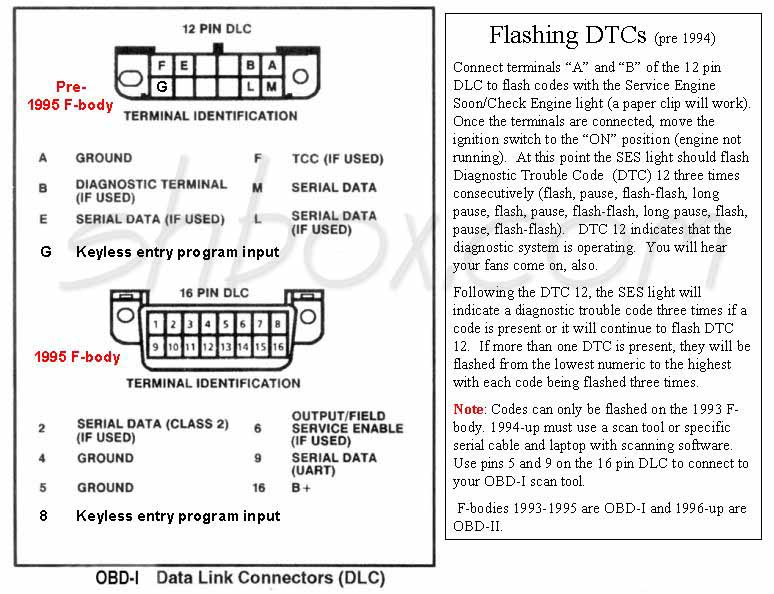
You can jumper two pins on the DLC that should cause the fans to come on. 1993-1994 cars with the 12 pin DLC can jumper pins A and B. On a 1993, that is the same way that you would retrieve trouble codes from the ecm. The 1994 won't give you any codes, but the fans will engage. 1995-1997 uses pins 5 and 6 on the 16 pin DLC to initiate what is called "field service enable mode". That will cause the fans to come on and operate most sensors for sanity checking. After placing the jumper on the correct pins, turn the key to ON (don't start). If the fans work after jumpering the DLC, your PCM is capable of operating the fans and all fan wiring/relays should be ok.
Deeper problems can be solved through testing and using the wiring schematic.
~Fans don't come on except when the a/c or SES is on~
~Temp gauge continues to rise with no automatic fan operation~
With a scan tool, check to see what temp the PCM is seeing from the sensor in the water pump. Make sure you are aware of the temps the fans come on (stated in the beginning of this article). If the temp it sees is incorrectly low, it won't know to turn the fans on. Another possibility is that the temp is really ok, but the gauge is reading wrong. That is why you need to use the scan tool to see and compare the readings. Info on testing wiring and sensor can be found here.
If that looks ok, then your PCM may have issues. You could always try resetting the PCM by pulling the PCM BAT fuse for about 30 seconds.
Other cooling issues
~Temps escalate with speed and fans are working~
Check for obstructions/debris in front of the a/c condensor (sometimes even between the condensor and radiator).
Make sure the air dam is on. Cars with low ground effects may need a special air dam to scoop up enough air for cooling.
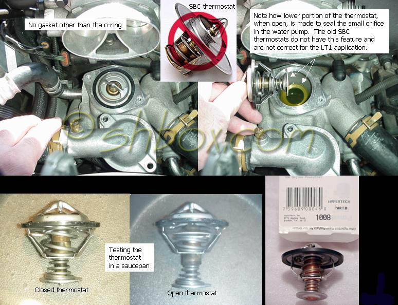
Check the thermostat for proper operation. It can be tested in a pan of water, heated on a stove. It should begin to open at it's rated temperature and then open fully as it gets warmer.
While on the subject of thermostats, the LT1 reverse flow system uses a special, long thermostat that works together with the passages in the water pump to provide proper coolant routing. If you use an old SBC style thermostat, you run the risk of the system not operating with proper efficiency and it may overheat.
Escalating temps can be caused by poor air or coolant flow.
~Generally running hot~
Examine system for any of the items mentioned above.
Check for air in the cooling system via the air bleed screws.
Check or replace the radiator cap (especially if you have heard lots of gurgling and overflow into the remote reservoir. The F-body system uses an 18 psi cap.
Check for any obvious leaks. If needed, rent a pressure tester that will allow you to pressurize the system while it is cool. This will allow you to see if it holds pressure and look for any leaks.
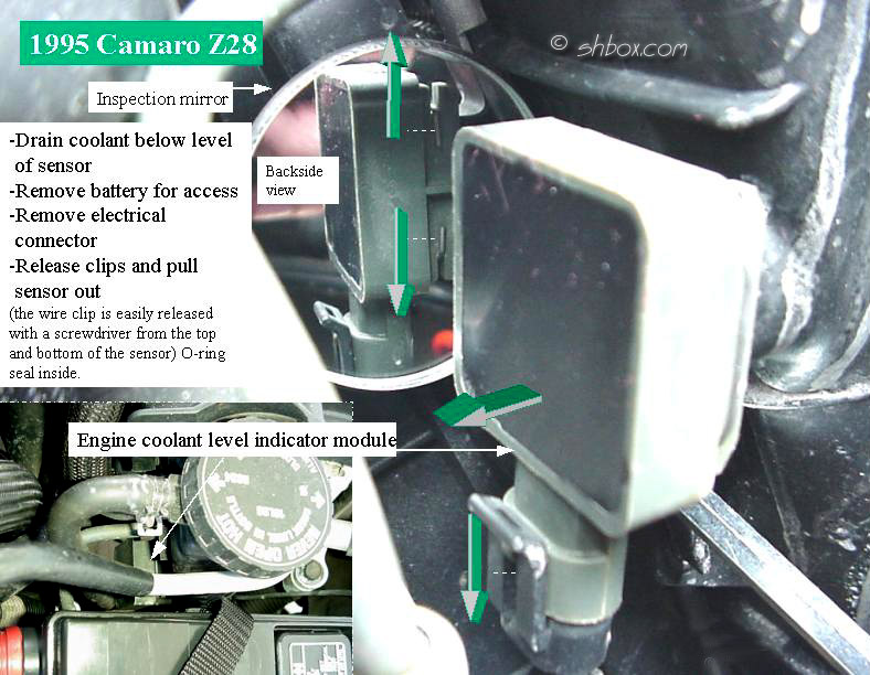
~Low coolant lamp on~
The low coolant sensor is a most common cause of complaint. If it gets dirty, it may cause the lamp to come on when the coolant level is actually ok. Sometimes it fails and no amount of cleaning will fix it. The sensor is only connected to the lamp on the dash. It does not report to the PCM and no DTC's will be set. Because of this, some people choose to simply unplug the sensor to get rid of the annoyance without having to fix it. Unplugging it will make the lamp go out, but you will have to monitor the coolant level yourself. As critical as the coolant is to the LT1, having it working makes sense.
If the light seems to come and go, make sure the level in the remote reservoir is proper. Normal operation of the cooling system often causes coolant from the radiator to overflow into the remote reservoir. As the engine cools down, the radiator creates a vacuum and pulls this coolant back into the radiator. The piping from the neck of the radiator to the reservoir must be air tight for this to occur. Since these cars are getting older, it is not uncommon to get a small leak in the pipe that goes under the battery. Acid wears away at the pipe until it makes a hole. Even a small hole is enough to cause problems. A telltale sign is a small amount of coolant under the right front of the car after it is parked a while. Usually, only taking out the battery will reveal where it is coming from, because it slowly drips on the splash panel underneath and may travel along to another area to drip off.
If the lamp is coming on for no apparent reason (you have verified coolant level is fine-that is, checked the level in a cold radiator and verified you have the proper level in the remote reservoir), you have a few choices:
Clean the sensor and connector and try it again
Replace the sensor
Unplug the sensor (the low coolant lamp will stay off and there will be no monitoring of the coolant level)
Thermostats and cooling
The temp rating of the thermostat is merely at what temp it will begin to open and allow coolant flow. It is purely a mechanical, temperature reactive device and has no external control or monitoring. A frequent reason behind a lower temp thermostat is to be able to make use of more aggressive spark advance without the engine having any spark knock (detonation or pinging). Excessive spark knock is detrimental to the engine. Spark knock is also monitored by the computer and timing advance is pulled (retarded) by the computer. When timing is retarded, performance and power will decline.
There is a fine line between between enough spark advance for high performance and the penalties for too much. The engine temperature plays a role in that the coolant wicks away heat from the combustion chambers in the head. Higher overall engine temperature results in higher overal combustion chamber temperatures.
Installing a lower temperature thermostat alone may actually decrease performance because a certain amount of heat is needed to burn the air/fuel mixture efficiently. If you see a decrease in gas mileage with a lower thermostat, alone, this may be the reason. The trick is to lower the temperatures but add enough timing to increase performance over what it was originally.
An often asked question is "Will my engine stay cooler with just a 160° thermostat?". The answer is yes, as long as there is good air flow across the radiator and the cooling system is working efficiently. Note that engine temps will still climb as they did before when you are stopped (as in traffic). However they may not rise as high, since you are starting out at a lower temperature than before. When you are moving again, it will be possible for the temps to lower more than what the 180° thermostat would previously allow. Cruising down the road, your engine should definitely stay cooler than before. Remember that the rated temperature of a thermostat is the temperature that it begins to open. While crusing on a moderate temperature day, an LT1 will generally run 10°-20° warmer than the thermostat temp rating. Make sure you use the correct, long LT1 thermostat (not an SBC thermostat) as described in the troubleshooting section above.
The thermostat only has control of opening temp to allow coolant flow, after that it does nothing but cause a predetermined amount of restriction in the flow. To make the most of the lower temperature thermostat, it should be accompanied by reprogramming of the fans, so that they will come on at a lower temperature. This will help to maintain a lower overall temperature in all driving conditions (especially when stopped in traffic). It is not mandatory that you do this and a 160º can be installed by itself with no other modification.
Something else to consider is that when the engine gets to ~220º (even before the stock fan ON temp of~226º) and you are at MAP loads of 70Kpa or more, the PCM begins to retard the timing. That is one reason why people feel their cars don't run well when they are hot. The GM folks built the retard into the spark tables because when the engine is hotter, there is more chance for spark knock. If you can keep the temperatures from getting up into that range, then you might feel more power when you need it.
Altering the fan ON temps can be done through reprogramming the computer or an aftermarket "fan switch" such as sold by SLP and JET . Manual fan switches can also be wired up to operate the fan relays so that the fans can be operated at any given time the driver wants (like in staging lanes). There are explanations on how to wire the manual switch up on the 'net and there are even a couple of wiring diagrams in the electrical section of my Tech Page. If you look at the fan schematics, you can probably see that there can be several solutions to operating the fans manually (my preference being to control the existing relays).
edited 4/9/2014
Easy Thermostat Changeout
Do this when the engine is cool (like after sitting overnight or for several hours where there is no residual pressure in the system). This way there will be no need to drain any extra coolant from the system.
You will have to remove the intake elbow.
Stuff absorbent rags or towels all around the thermostat housing to catch any coolant when you take the housing loose. Not a lot will come out. Just keep it off your optispark. Swap the thermostats and put the housing back on. Don't overtighten the bolts, they can easily break (torque to 89 lb. in. - "snug"). No gasket or sealant is needed other than the rubber o-ring that is on the thermostat, itself.
Put everything back together and put whatever amount of coolant you lost back into the remote reservoir. You can also top off the radiator, if you wish. After a few heat and cool cycles, the system will pull back in any coolant that was lost.
Idle the engine and monitor the temp. If the temp quickly goes abnormally high, you may have an air pocket. Open the bleeder screws after the thermostat is open to remove any air. Only a stream of coolant will come out when all air is gone and there will be no spitting or hissing. You can also refer to the refill portrion of the drain and refill procedure, if you want to try to purge air again when the engine is cold.
Close screws and monitor the temp.
3/14/2011
T-56 Repair Manual
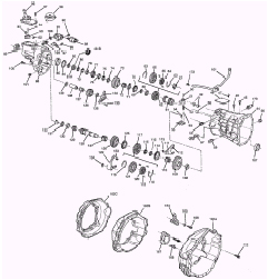
T56 Service Manual (pdf format)
Right click if you want to download and save
Left click to view online
Adjusting Valves and Zero Lash
Zero lash is when you go from having slack between the lifter, pushrod and rocker arm, to the exact point of no slack. The lifter needs to be on the base of the lobe when setting valve lash. When a cylinder is at TDC, both lifters should be at the bottom of their travel (base of the cam lobe).
Gauging zero lash by hand is not an exact science. When setting the valve lash with the engine not running, you can get close enough by doing the "spin the pushrod" method. Loosen the rocker arm until you can feel slack in the pushrod to rocker arm. Spin the pushrod with your fingers while tighening the rocker arm back down. The instant you BEGIN to feel drag while spinning the pushrod, you are at zero lash. Pay close attention. If you get it too tight, loosen and retry. If you don't like the spin method, use the up/down slack method of gauging when the slack is gone. Once zero lash is reached, stop and add your preload. DO NOT go back and try to feel the adjustment again. The lifter will immediately begin to bleed down a little. Tension on the pushrod will relax and this will make it seem like your adjustment did not work. If you want to recheck zero lash, you must loosen the rocker arm nut and tighten it down again while manipulating the pushrod as before. At that point you want to set the preload and LEAVE IT ALONE.
The hydraulic lifter has an internal plunger that has a specific amount of travel. On stock engines, the purpose of preload is to compress the plunger so the pushrod will be riding on a "cushion" (acts like a shock absorber). With stock lifters, turning the rocker nut another ½ to ¾ turn, will normally put you in the ballpark for quiet operation without being too tight and the adjustment should last a long time. Most books show stock preload at up to 1 turn. Specific lifters like the Comp Cams "Comp R's", have less internal travel. ¼ turn preload is more than plenty, with 1/8 or just barely any preload being better for high revving engines. Comp actually recommends .002-.004 preload on a warm engine for those lifters.
For reference:
3/8" stud: ½ flat = .003472"
7/16" stud: ½ flat = .00416"
Rotating the nut 1/6 of a turn (until the next flat side is in the same position as the previous flat side) is a "flat".
Consequences of improper adjustment:
Too tight - the valves will not completely close and you will lose compression. The engine will run rough, if it will run at all.
Too loose - the rocker arms will make noise from the slack and pushrods could be dislodged. Possible damage could occur from either extreme.
Engine Running Method
Some like to adjust the rockers while the car is idling. If you wish to do this, loosen one rocker at a time until you can hear it click. Tighten the nut, but don't exert downward pressure on the rocker arm with your socket or wrench. At the point when audible clicking is gone, tighten the nut another 1/4 turn (or whatever desired) for your preload (Comp R lifters, less as noted above).
Engine Not Running Methods
There are several methods for setting the lash with the engine not running and are listed below. Read through them all. You might prefer one method over another. They all accomplish the same thing. Method 3 is the most foolproof, but the most time consuming and will work well for very agressive cams. I have personally used method 1 for many years without any issues.
Method 1
If you have never had the crank hub off (or know for sure that it's orientation is correct), you can use the arrow that is on the balancer to tell you where you are. You don't have to spin the crank every 90º with this method.
When the arrow is at 12 o'clock you will be at either #1 or #6 TDC. You might have trouble identifying whether #1 or #6 is at TDC when the crank arrow is at 12 o'clock. Probably the easiest way is to look over the other valves or lifter positions. Compare them to the charts below, showing which can be adjusted. Any valve that can be adjusted should be UP (closed) and the lifter/pushrod should be down. Valves that are not to be adjusted will be in varying degrees of being open or DOWN (lifters/pushrods UP). I used to recommend looking at the valves on the #1 and #6 cylinders, but sometimes it can be difficult to tell by those cylinders only. After looking at the charts below and your valves or lifters/pushrods, you should have it figured out rather quickly.
Valve postions are the same front to back or back to front: E - I - I - E - E - I - I - E
When at #1 TDC you can adjust the following valves:
Intake: 1, 2, 5, 7
Exhaust: 1, 3, 4, 8
Rotate the crank one revolution until the pointer is again at 12 o'clock. This will let you adjust the remainder of the valves. If you did #1 the previous time, you should be now at #6 TDC.
When at #6 TDC you can adjust the following valves:
Intake: 3, 4, 6, 8
Exhaust: 2, 5, 6, 7
Method 2
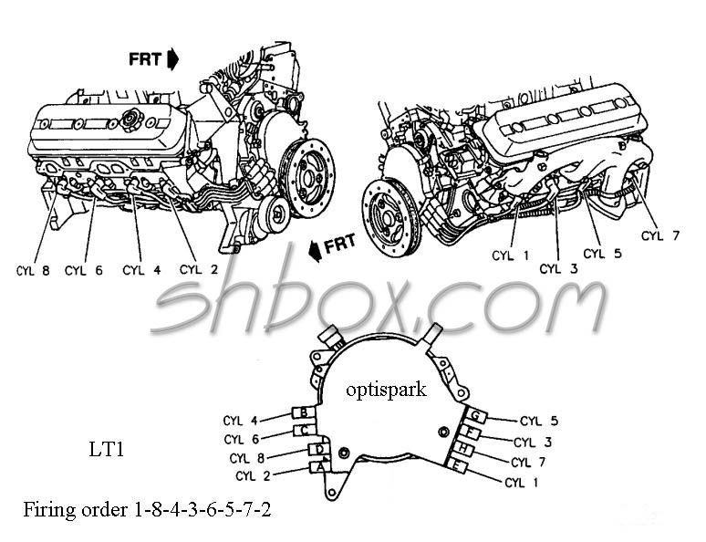
If you want to set the lash by bringing each cylinder to TDC, watch the valves and the pointer on the balancer and follow the Firing order:
1-8-4-3
6-5-7-2
Adjust both intake and exhaust of the cylinder that is at TDC. You will have to make 2 revolutions of the crank, stopping at 1/4 (90º) turn intervals for each cylinder.
Method 3
Another cylinder by cylinder method that does not require looking at the balancer position, follows:
(A remote starter switch is quite helpful)
Turn the engine in the normal direction of rotation until the exhaust lifter for the cylinder you are adjusting starts to move up (valve begins to open).
On the intake rocker arm, adjust for zero lash and add your desired preload.
Turn the engine over again until the intake lifter on the same cylinder comes all the way up (valve open) and then goes almost all the way back down (valve almost closed) .
Now, adjust the rocker arm for the exhaust valve on that cylinder to zero lash and add your desired preload.
Continue the above procedure for each cylinder until all valves are adjusted to the same amount of preload. This procedure will work for any hydraulic lifter cam with adjustable rocker arms. Refer to this diagram posted above if you need visual reference. The reason I specify lifter movement in the above is because when you start off with completely loose rockers, there is no valve movement to watch.
Here is something additional for those that use "poly locks" (typically used with roller rockers).
Since the poly lock is not a prevailing torque fastener like the nut used with the stock rocker and ball arrangement, it spins freely on the rocker stud. This gives you an advantage to finding zero lash. With the allen lock backed off, spin down the nut until it just stops. This is very close, if not right on zero lash in most cases. Check your pushrod for proper movement and play with it to get a feeling just how snug or loose the nut should be to obtain zero lash. Once you do that, you can just use the nut to reach zero lash and not have to worry about messing with the troublesome pushrod. This will speed up your valve adjustment.
Another aid is to make a mark on the top of the nut so that you can easily see how far you have turned the nut. I always found it a little difficult to obtain the exact amount of rotation on the nuts under the cowl, because of there being less room to swing a ratchet or other tool handle. I used a little dab of white paint on the top and was easily able to tell when I made a half turn or whatever was needed. Now, I can just use a wrench to tighten the nuts, then throw the allen wrench on it and snug the set screw down (while holding the nut).
Some like to run the allen set screw down and then tighten it and the nut together. If you overdo it this way, you may break the nut. I always have good luck with setting the nut and then the set screw (never had one come loose). With all the variables in making adjustments to hydraulic lifters like the number of turns for preload, methods of finding zero lash and trying to see what you are doing under the cowl, slight errors are common. Just try to be as consistent as possible and use the method that works best for you.
edited 3/21/2013
Cam Timing
Cam timing animated gif
left click to view or right click to download
OPTI and Spark Test
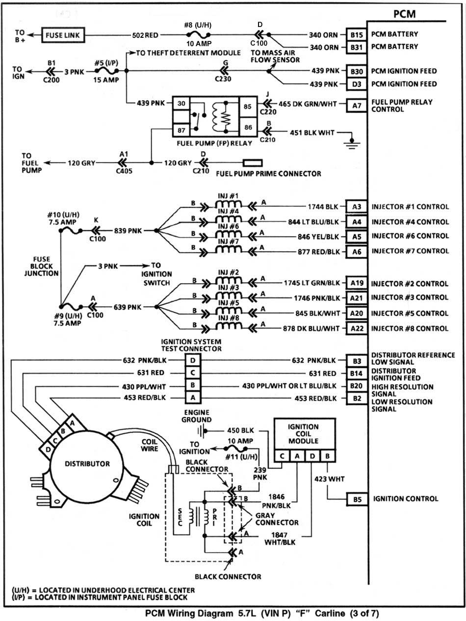
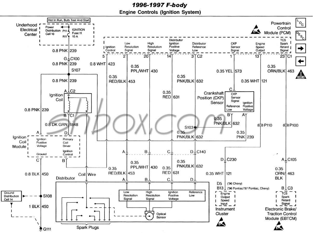
Trouble codes 16, P0323 for low resolution or 36, P0372 for high resolution may lead you to this procedure. Though, note that the low resolution code does not cause the Check Engine light to come on. So, you may have opti troubles without a light on the dash. A hard low resolution signal failure will not allow engine operation (no spark, no fuel injector pulses, no fuel pump operation [except prime]). Intermittent low resolution failure will consequently cause intermittent engine operation or stumbling. High resolution codes do cause the light to come on and engine will often continue to run (but maybe not as it should at all times).
The opti has two functions in the spark process. The first thing that happens is as the cam turns, the optical section of the optispark picks up the signals by the rotation of the shutter wheel. The pulses are sent to the PCM via the optispark electrical harness. The PCM processes the signals along with other sensor input and determines the proper time for the coil to fire. The PCM sends a signal to the Ignition Control Module (ICM) and it, in turn, causes the coil to fire. The spark from the coil travels through the coil wire back to the secondary ignition section of the optispark (cap and rotor), to be distributed to the proper cylinder.
Remember, if the opti is never sending the signal to the PCM, the PCM will never send a signal to fire the coil or generate any injector pulses.
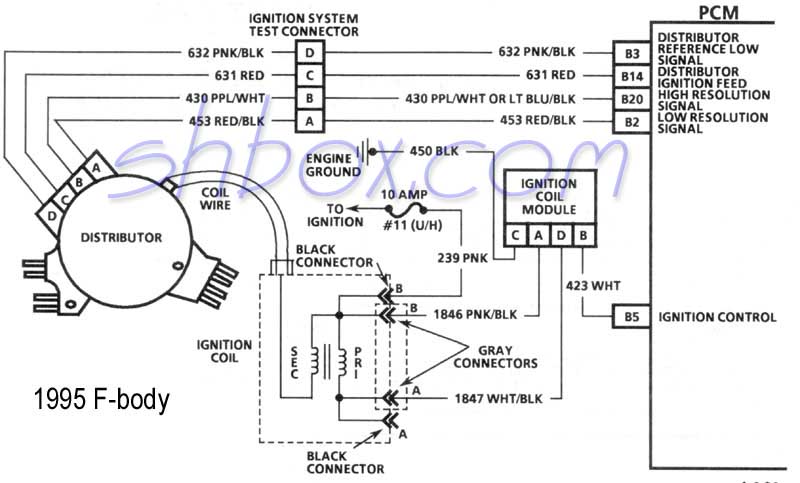
Here is some testing you can do. Refer to this diagram for 94-95s. 93 and 96-97 ignition system diagrams are slightly different overall, but the ICM connector is the same. Note: Pay attention to the fact that the diagram may show A-B-C-D out of order for ease of diagramming. They are actually in proper order on the physical connector. The connector has the letters embossed on it, so make sure you are testing the correct one.
Disconnect the ICM connector. Leave coil connected (important).
Turn key to ON.
Check for dc voltage with a digital meter at harness terminal "A" to ground and and also "D" to ground. Note: Use a modern digital meter with at least 10 megohm impedance to protect the PCM (in case you measure anything in that direction). Do not use a test light for looking at voltage potentials from electronics! Also make sure your meter leads make good contact and are clean and tight. Check that you get a zero ohms reading by touching the two leads together. If it is not zero, merely adjust the readings you take by the skew. That will ensure accurate resistance readings.
Result should be 10v dc or more on the A and D terminals. If you get no voltage, use the diagram and chase back toward the coil and the ignition fuse. Power for the ICM comes from the ignition fuse and through the coil, so any of that could be bad.
If you have good voltage, switch the meter to ac scale and connect test leads to terminal "B" and to ground. Observe meter while cranking the engine. You should see between 1 and 4 volts ac (those are the pulses that trigger the coil to fire).
If you don't see the proper ac voltage the problem could be the optispark, the harness to the optispark, the PCM (not common) or any of the wiring in between. Visually inspect all the connections for possible poor contact or corrosion.
You should also check "C" of the ICM harness for continuity to ground.
ICM Harness
A = ~10vdc-12vdc (or your system voltage)
B = 1vac-4vac while cranking
C = ~ 0 ohms to ground with key OFF
D = ~10vdc-12vdc (or your system voltage-might be slightly less than reading at "A")
At the end of the optispark harness (disconnected from the opti) with the key ON, you should see:
Optispark Harness
A = ~5vdc
B = ~5vdc
C = ~12vdc (or your system voltage)
D = ~0 - 0.2 ohms ground with key OFF
If you have the means, looking at the low and high resolution signals from the opti to the PCM with an oscilloscope is probably the best way to tell their health.
edited 9/19/2023
Pass Key II® Key Pellet Values
|
Pellet Code
|
Key Resistance in Ohms
|
|
|
Nominal
|
Low
|
High
|
|
1
|
402
|
386
|
438
|
|
2
|
523
|
502
|
564
|
|
3
|
681
|
654
|
728
|
|
4
|
887
|
852
|
942
|
|
5
|
1130
|
1085
|
1195
|
|
6
|
1470
|
1411
|
1549
|
|
7
|
1870
|
1795
|
1965
|
|
8
|
2370
|
2275
|
2485
|
|
9
|
3010
|
2890
|
3150
|
|
10
|
3740
|
3590
|
3910
|
|
11
|
4750
|
4560
|
4960
|
|
12
|
6040
|
5798
|
6302
|
|
13
|
7500
|
7200
|
7820
|
|
14
|
9530
|
9149
|
9931
|
|
15
|
11800
|
11328
|
12292
|
Use a multimeter to check the resistance of the pellet in the key and compare to the table above. Touch the meter leads to each side of the pellet on the metal bar. The nominal reading is the ideal reading. It most likely will be in the range delimited by "low" and "high". There are 15 different key pellets used. Use this information when you need to get a new key made or for finding a resistor if you wish to bypass the system.
edited 1/24/2005
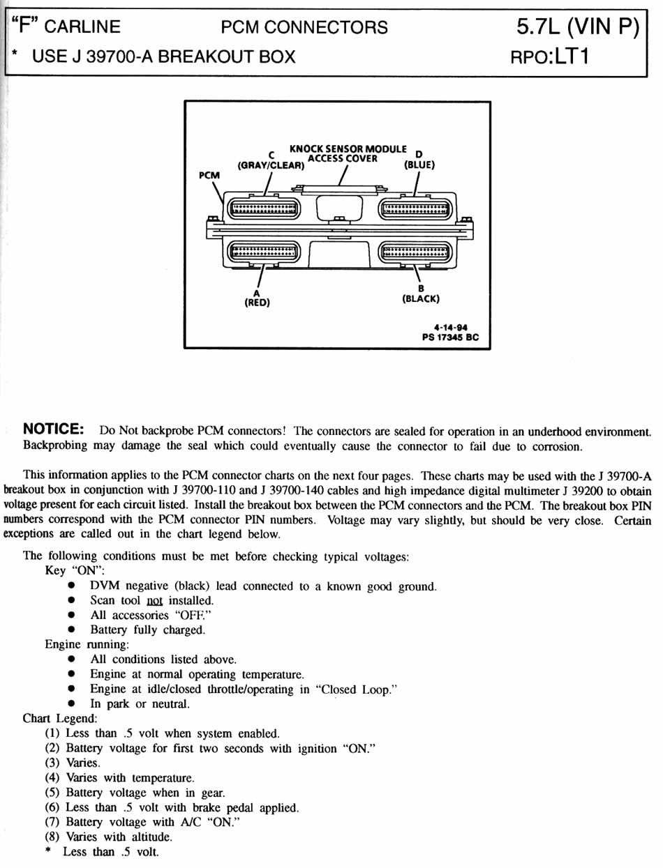
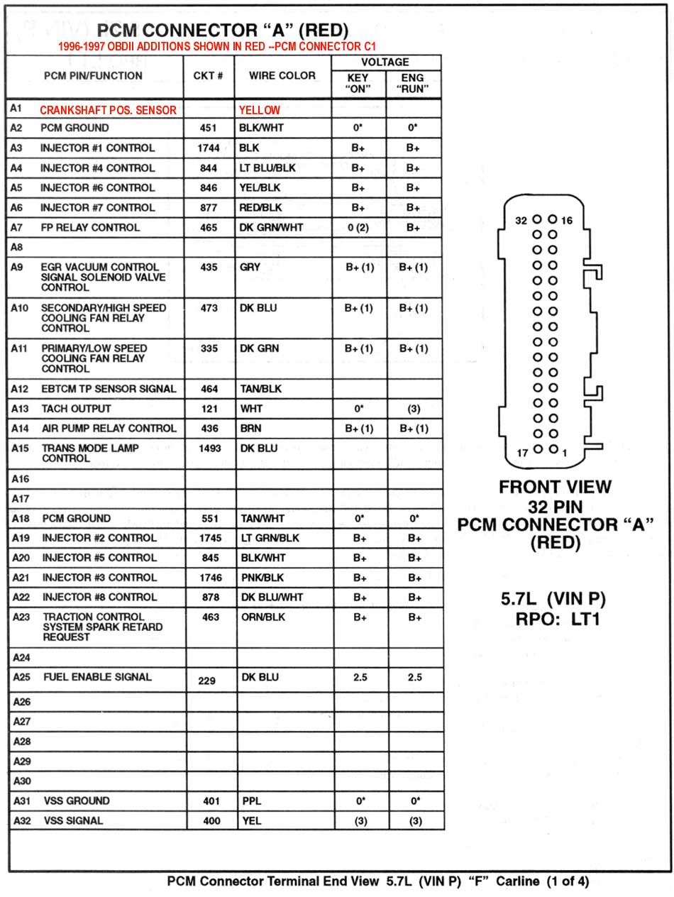
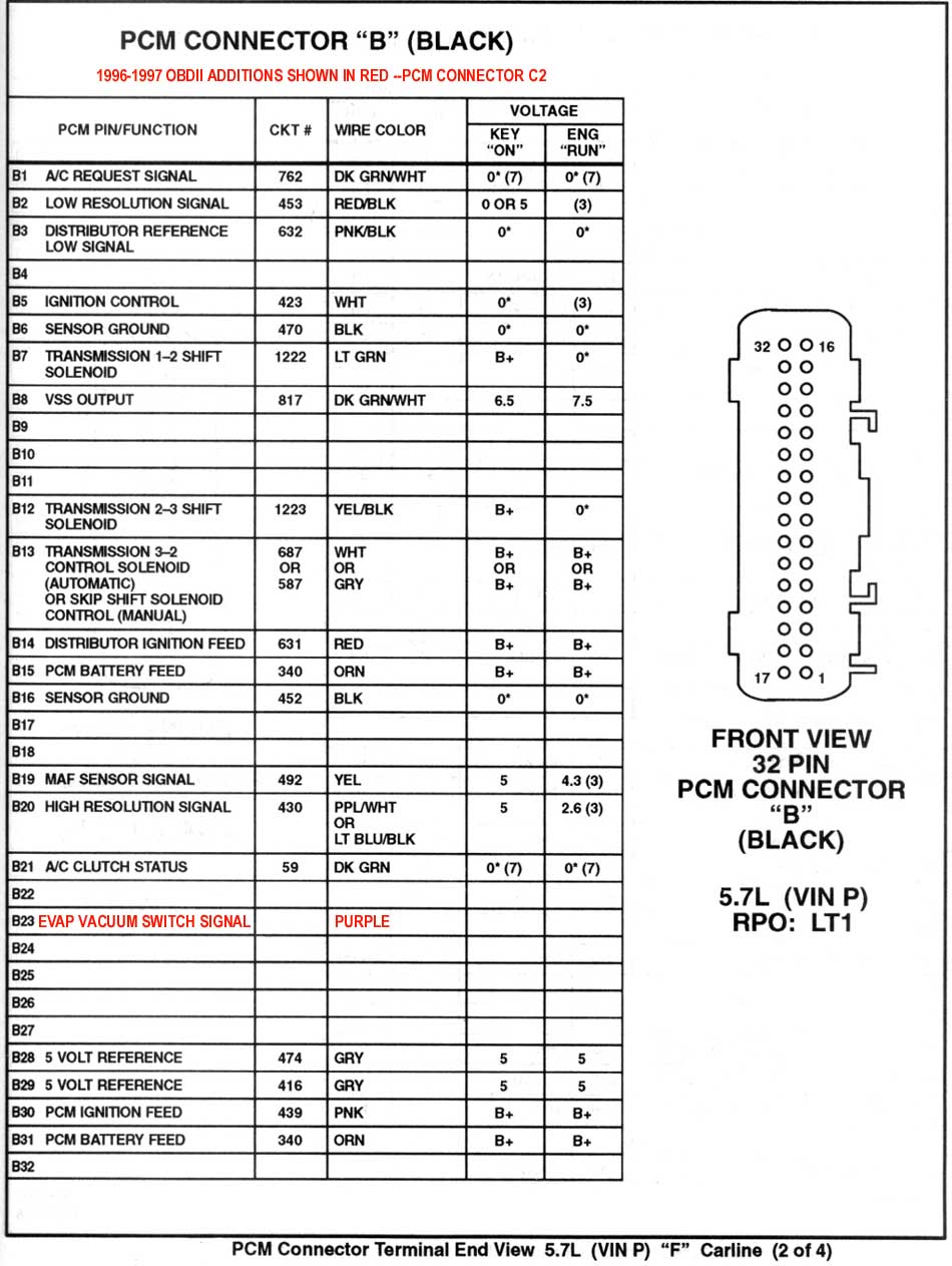
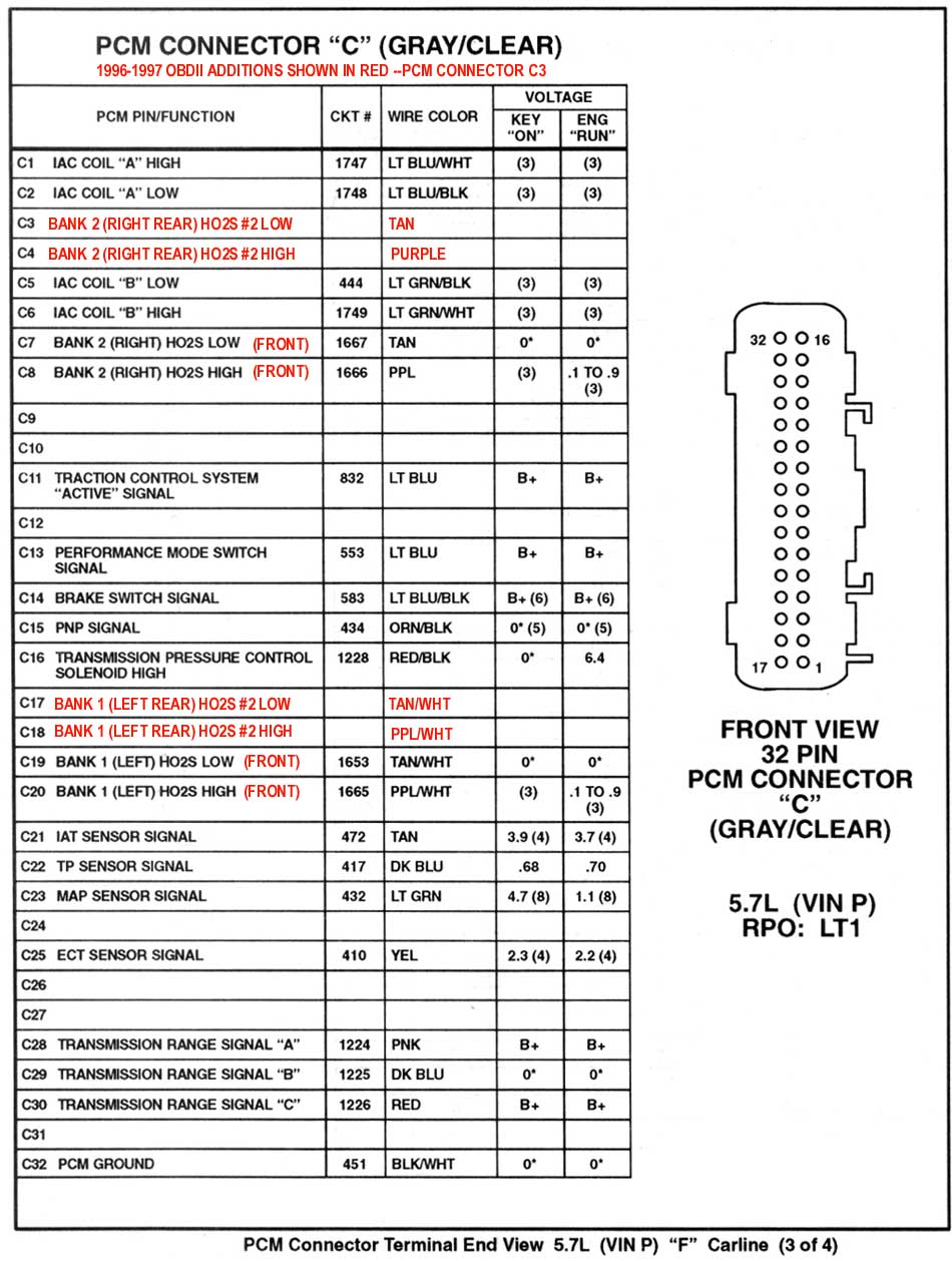
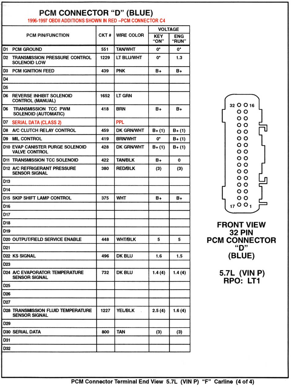
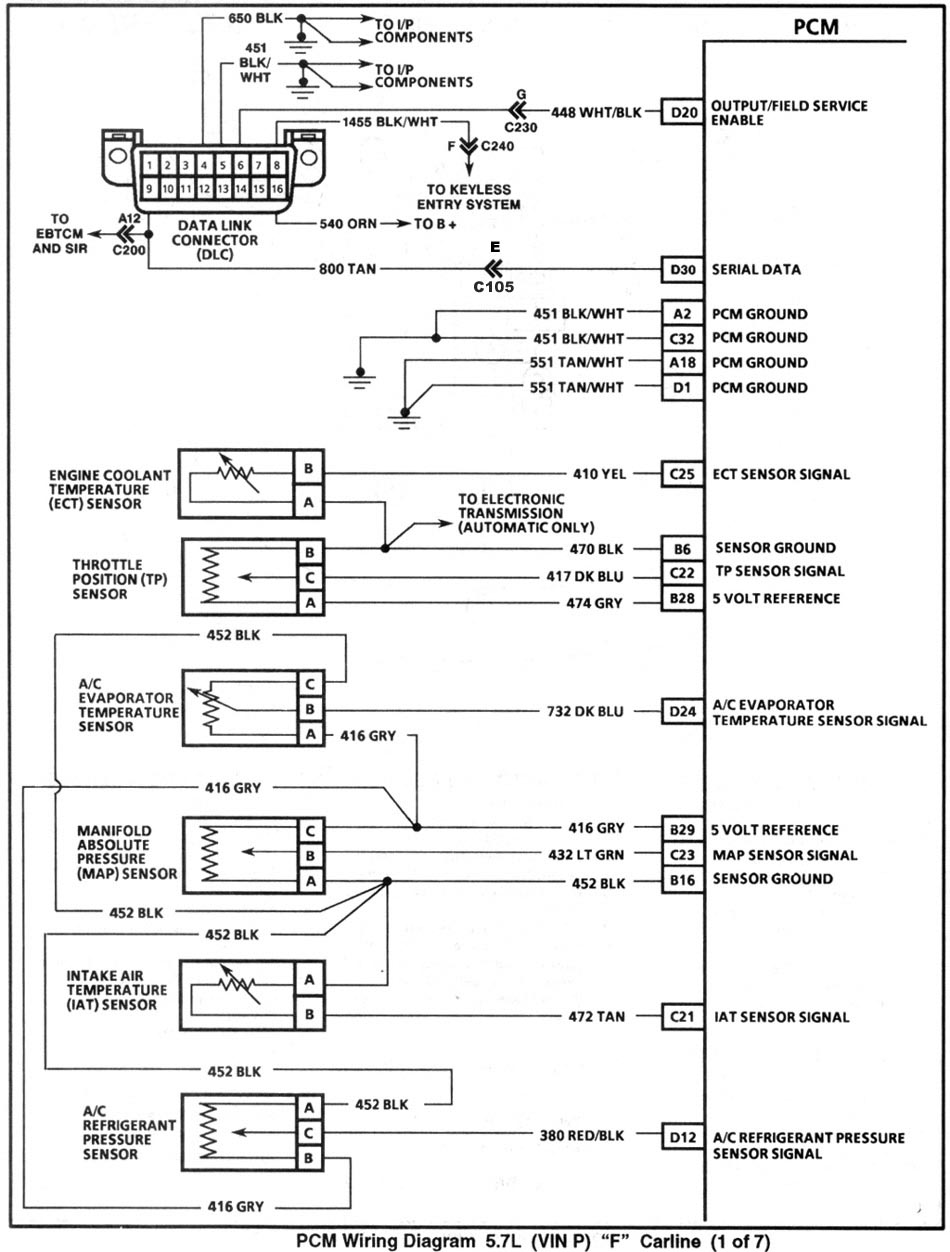
1995 PCM Pinouts
1995 PCM Wiring
ICM Cooling Mod
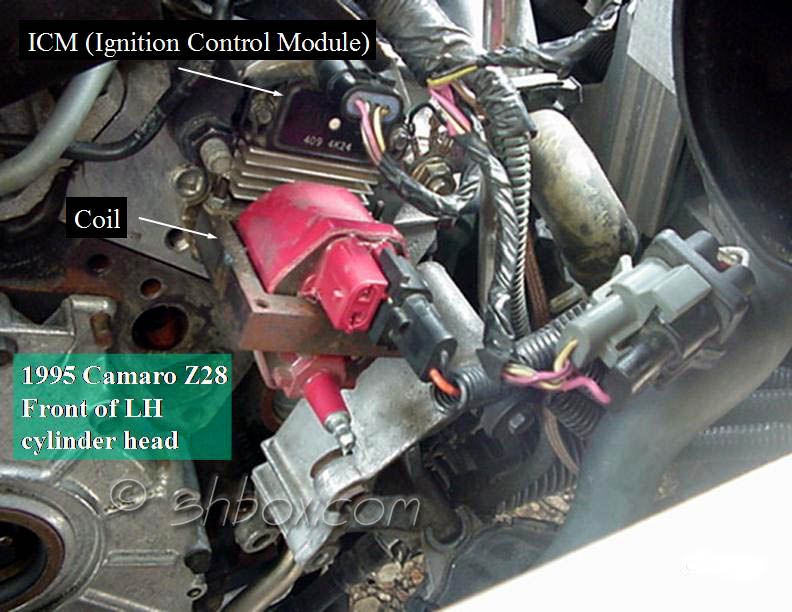
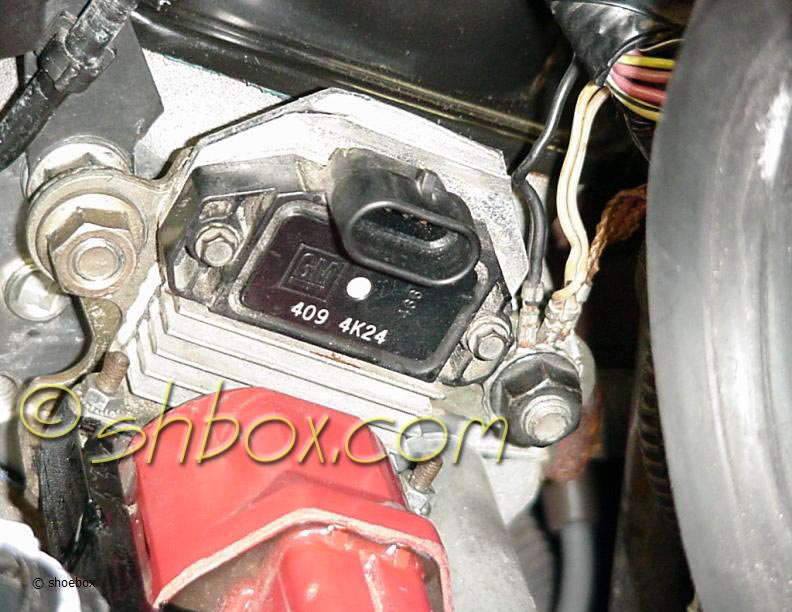
Some people have reported ignition problems that seem to be heat related. One item that can be relieved of some heat stress is the Ignition Control Module (ICM). Merely spacing the coil and ICM bracket away from the cylinder head has solved miss problems in some cases. Any time you can reduce the amount of heat in an electronic component, it will normally prolong it's life and allow for more stable operation.
Getting to the coil and coil replacement is covered elsewhere in my Tech Pages, so I am not going to step through that procedure.
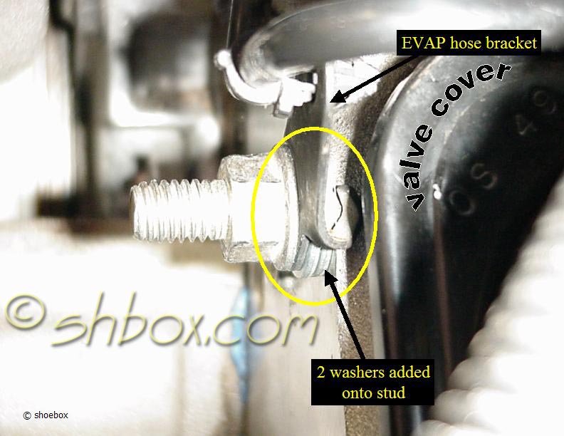
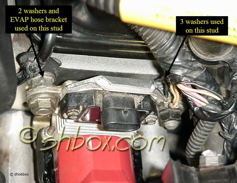
On my 1995 Z, I used a very simple approach to creating some space between the coil bracket and the head. I used some common 3/8" flat washers that I already had laying around. After removing the coil and studs, I put 2 washers between the "stud nut" and the cylinder head on the inboard stud. There is also a bracket for the EVAP hose that goes on this stud to take up some room. I used 3 washers on the outboard stud. With the thickness of the washers I had, this made the distance on each stud approximately the same (approximately 3/16").
The washers are used, because without the coil bracket sandwiched on the stud, the threads would bottom out in the head. This just gives a little extra space, which is not a problem.
Once the washers are in place and the studs screwed back in, you can mount the coil on the outside of the stud nut, instead of the inside where it was before. Torque value for both the stud to head and the nut is 18 lb. ft.
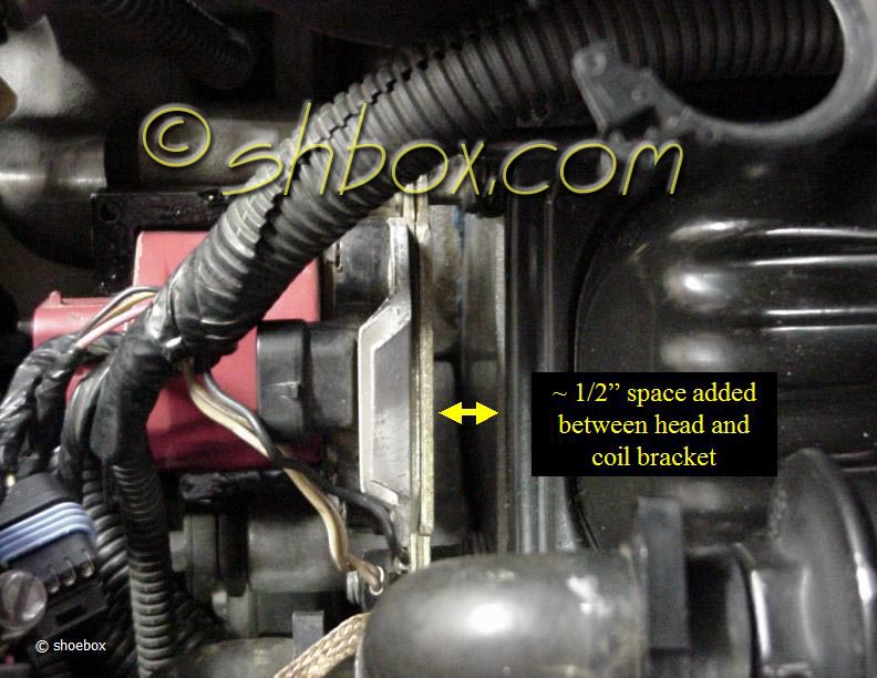
The total gap came out to about 1/2". Note that one of the studs has more threads on the outside portion of the stud nut. This is the stud that goes in the outboard head hole and is longer to accomodate the ground straps attached to it.
Another note: 1993 owners may have a bolt instead of a stud on the inboard side and others may have identical studs on both sides. It really does not matter. The intent is to create an air space between the head and the coil bracket. A little ingenuity and a couple of additional fasteners may be needed.
Tighten up the fasteners and reconnect electrical harnesses and you are done. I don't have any dyno runs or temperature comparisons for before and after, but for next to nothing in cost, this mod can't hurt.
I am not the first one to do this and it could be done using other methods and materials (perhaps, even more effectively). This just happens to be the way I did mine.
Update: At least one person monitored the temperature of the ICM and the head after the mod. With the engine running, the ICM stayed cooler, but when the engine was turned off, the ICM did not dissipate heat as fast as the head did. I did not get any info on how long the ICM stayed hotter. I am just providing that for your information and you can draw your own conclusions.
5/10/2003
Compression Test
Engine should be warm, if possible.
Remove the ignition fuse to kill spark and the injector fuses to kill fuel.
Remove all the plugs. This keeps other cylinders from building compression and affecting the cylinder under test.
Remove intake elbow and block the throttle wide open. This lets the engine spin freely without trying to create vacuum.
Install compression gauge to cylinder to be tested.
Crank engine through 4 compression cycles. The engine will crank a little faster with all the plugs out.
Watch the gauge during each stroke. Normal compression builds up quick and even.
Record readings if you are searching for a bad cylinder and to be able to compare readings. General specs are that the lowest cylinder not be less than 70% of the highest and no cylinder less than 100 psi.
Put everything back to normal when you are done. Be sure you unblock the throttle!
If you have issues you need to track further, a leakdown test will be able to tell you whether rings, valves or head gasket might be leaking.
edited 9/28/2010
Checking Pressure Loss in the Fuel System
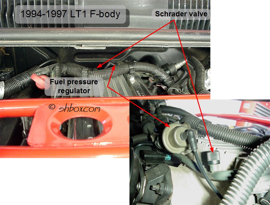
A fuel pressure test gauge can be bought at your local auto supply for ~$35. Attach it to the schrader valve that is on the fuel rail. Schrader valve location on 1994-1997
Normal pressure when the engine is not running and lines have been pressurized is 41-47 psi. This same pressure should be observed at wide open throttle (WOT). Removing the vacuum hose to the regulator at idle "simulates" the same vacuum condition as during WOT (but is not a substitute for WOT testing as noted in the next paragraph). At idle (because of the effect of the vacuum to the regulator) pressure will be less than what you observe with the vacuum line off (less pressure is needed at idle because of the lesser demand). There may be anything from a 3 to 10 psi difference. Note: any indication of fuel in the vacuum line to the regulator, means the regulator is leaking and should be replaced. Check the line for fuel or the smell of fuel.
To fully determine that you don't have a pressure drop off during actual WOT situations, you should tape the gauge to your windshield and take it for a test run. This will tell you if the pump can meet actual fuel flow demands at pressure and not just at a "simulated" WOT condition (as when removing the vacuum to the regulator).
When you have a gauge connected and the pressure looks initially good and then bleeds off quickly when you shut the engine off, you can do a couple of tests to help you figure out where the pressure loss is.
What the factory manual says to temporarily install, is a set of "fuel line shut off adapters" (probably something the normal guy is not going to have available). You remove the fuel lines from the rail and connect these valves in between. This lets you shut off either side of the lines for testing.
You can do the same thing by pinching the flexible lines to shut them off, but risk breaking them. You might be able to do it (your risk) by using a needle nose vise grips and putting some scrap hose as cushions on the jaws. Then use that to clamp off the line just enough to seal it. Obviously, this is not the best way to shut off the lines and could result in breakage. Heat and age can make the hoses brittle. If you don't want to risk it, don't. It's just a suggestion.
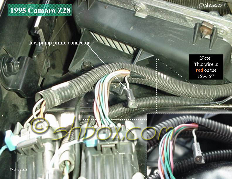
You can use the fuel pump prime connector for pressurizing the system (jumper 12v to it to run the pump).
Watch your gauge as you jumper the prime connector. When you have good pressure remove the jumper and clamp off (or use shut off valve) the fuel supply line (3/8 pipe). If pressure holds, you have a leak on the feed line somewhere before it gets to the clamp (or shut off valve) or at the check ball in the pump.
If it still goes down, release your clamp (or open shut off valve). Pressurize the system again, then remove the jumper and this time clamp (or shut off) the return line (5/16 line). If pressure holds, then the regulator is faulty. If pressure does not hold, you need to locate leaky injector(s).
If you can't tell a leaky injector from reading the plugs, you can look and see if injectors are leaking by removing the fuel rail screws and pull the rail and all the injectors up, so you can see under them. Leave them over the injector ports. Pressurized the system and look under the injectors to see if any are dripping.
edited 7/11/2010
Fuel Gauge Operation and Testing
Most people notice that the fuel gauge does not read in a linear fashion. It will stay on the full side for a long time and then once it starts moving, it will drop rapidly. This is due to the shape of the tank and the placement of the float assembly/gauge sender unit. The tank has a bit of a wedge shape to it, that causes there to be more volume in the upper part of the tank than in the lower. The float only reacts to an up and down level and does not compensate for the tank shape.
Typically, when the gauge reads:
way past full=full tank
¾ = about half full
½ = about a quarter full
¼ = a couple gallons
E = very little on most cars (gallon or less), can be really empty on some
Tank capacity is 15.5 gallons.
Avoid running your car out of fuel! The fuel also acts to keep the pump cool. Running out of fuel can trigger a pump failure.
If you are having a problem not related to the "normal" way the gauge acts as stated above, there are some things you can check.
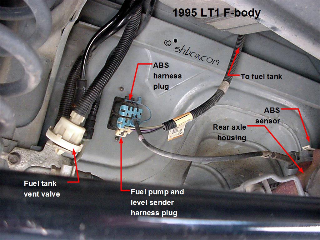
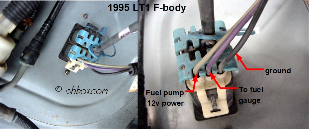
Locate the pump electrical connector on the rear of the floor pan under the car (above the LH axle tube). It has purple, gray and black wires going toward the fuel tank. Unplug the connector. With a meter set to ohms, read resistance between the black and purple wires going to the tank.
approximate:
88 ohms = full
60 ohms = 3/4
43 ohms = 1/2
26 ohms = 1/4
1 ohm = empty
The readings should correspond to your gauge. If the reading(s) seem accurate to what you have in the tank, the sender is ok. If they don't, the sender or wiring from that connector to the sender has a problem.
To test back to the gauge, ground the purple wire on the body side of the connector back toward the gauge (key ON). The gauge should read empty. With the connector unplugged and no ground applied, the gauge should read full.
edited 3/15/2009
Reset the IAC Position
- Depress accelerator slightly
- Start engine, then release accelerator pedal, run engine for 5 seconds
- Turn ignition "OFF" for ten seconds
- Restart engine and check for proper idle operation
It is NOT recommended to to push or pull on the pintle of an IAC that has been in service. The force required can damage the threads on the worm drive. Also, do not soak the IAC in any liquid cleaner or solvent, as damage may result.
When installing a new IAC, you may move the pintle to match the measurement of the old one. The force required to move a NEW valve will not cause damage to it. Use engine oil to lubricate the o-ring. Tighten attaching screws to 27 lb. in.
Note that the 1993 IAC has a square electrical connector and the valve screws into the throttle body, instead of being held on by screws like those of later years.
edited 4/15/04
Restore Airflow to the Dashboard Vents
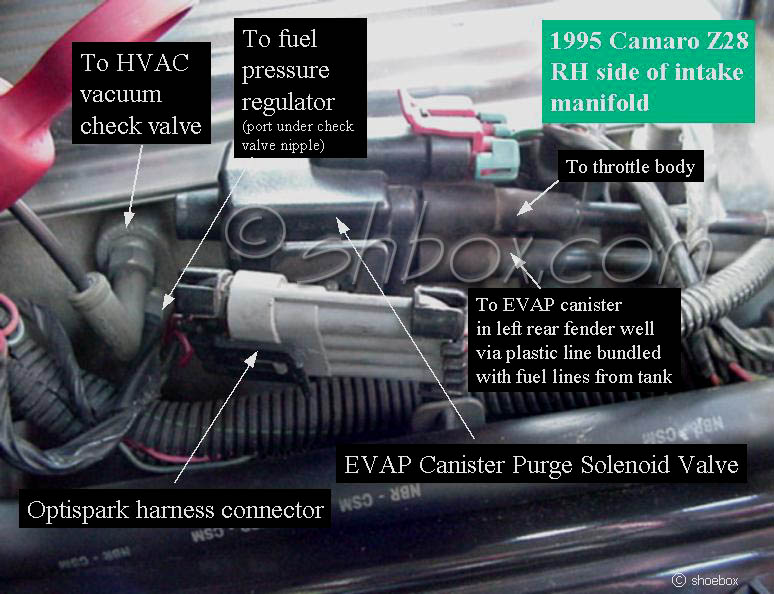
This is a common fix for when the air no longer blows out the vents. When there is not enough vacuum to operate the actuators, they will only direct air to the floor and defrost ducts by default. Diagram of HVAC system. You may also notice this happening under hard acceleration or going up a long, steep hill (times when engine load is high and vacuum is low). This might mean you have a small leak.
An easy way to tell what part of the system may have trouble is to go to the vacuum check valve and test the lines back to the mode selector, intake manifold and to the vacuum tank. The check valve often cracks and is the source of a leak, so be sure to inspect and/or test it. Note: the vacuum check valve is now GM part #15733271. The line to the vacuum tank can often get a hole just under the battery box. It can rub where it passes through the chassis and/or deteriorate from battery acid contamination.
A hand held vacuum pump (like a Mityvac), makes testing pretty easy (your lungs can be used as an alternate vacuum source ;-) or you can blow through the lines and listen for air escaping). At the check valve, remove the hoses one at a time and apply vacuum to each and see if it holds. The line to the intake manifold will have to be removed at the manifold and plugged back toward the check valve for you to test the line for leaks. If you find a leak on a particular hose, you will have to trace out the cause on that section.
edited 8/31/2019
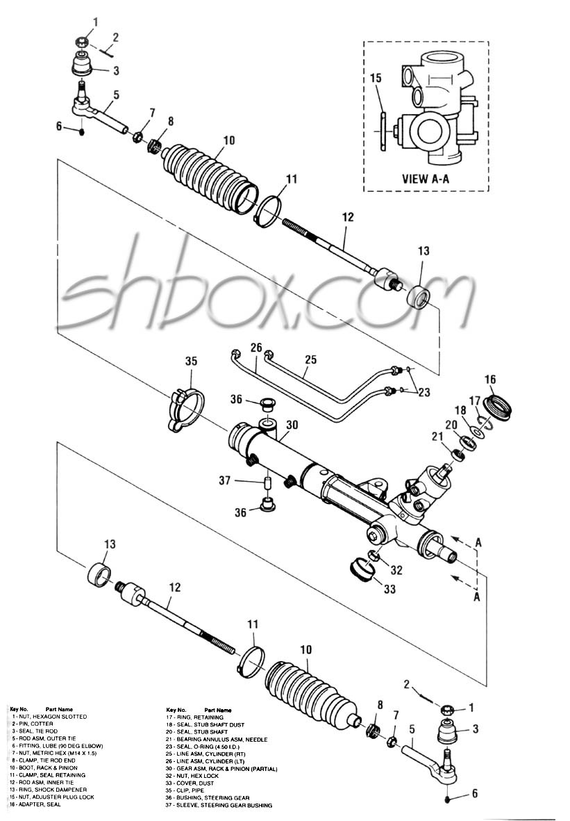
Adjust Steering Rack Bearing Preload
Make late model wheels fit on your early model 4th gen
Late model 1998 and up axles used a smaller hub center on the rear axles. Therefore the wheels were made with a smaller hub opening on the back. When you try to swap these wheels onto an earlier model 4th gen, the center of the wheel won't fit over the rear axle hub.
The back side of the hub area on the wheel has to be relieved a small amount to allow it to slip on. You can dry fit the wheel to "mark" where the interference is, then you will be able to see the area that needs attention. Use a Dremel, sandpaper or even a half-round file to take off the little bit that is required. It does not have to be perfect, as the wheels are centered by the conical lug nuts, not the hub and that part of the wheel is never visible. Just relieve it enough to get the wheel on/off easily.
If you ever intend to rotate your tires, you will want to do this to all four wheels (The fronts will fit without any modification. There are no clearance issues with them). Don't ever try to force the wheel on with the lug nuts. You can strip lug studs and/or get the wheel stuck.
How many catalytic converters and oxygen sensors should my LT1 f-body have
and is it OBD-I or OBD-II?
1993-1995 LT1 f-body cars have one cat, with the exception being California Emissions (RPO NB6) A4 cars having two. All 1995 M6 cars have one cat.
1996-1997 f-body cars have two cats.
1993-1995 LT1 f-body cars are all OBD-I (regardless of how many cats they have).
1993 LT1 f-body cars can flash trouble codes by shorting 2 pins in the DLC and observing the Service Engine Soon lamp (like most earlier model GMs). 1994 and later must use a scan tool. The computers changed from ECM (Engine Control Module) in 1993 to PCM (Powertrain Control Module) in 1994 and later (adding electronic transmission control). Though 1993 and 1994 were both OBD-I, they used different computers. 1993s used the replaceable chip type (PROM), while 1994 and up used flash memory for storing the program (EEPROM).
1996-1997 LT1 f-body cars are OBD-II.
1993 LT1 f-body cars have two 1 wire, non-heated O2 sensors. 1994-1997 have two 4 wire, heated O2 sensors (with 1996-97 cars having two additional rear (post cat) O2s to comply with OBD-II). On the f-body, front O2s use a flat connector. When rear O2s are present, they use a square connector.
The only 1995 f-body engine that is OBD-II is the 3.8L V6 that came out during the model year (replacing the 3.4L V6 that was OBD-I).
RPO NA5 = Federal Emissions System
RPO NB6 = California Emissions System
edited 8/13/2010
Requirements for Converting to a Vented Optispark
If you want to change to a vented from non-vented optispark, you have to do many things. It may not be cost effective unless you are doing a cam swap at the same time.
Besides the vented optispark itself (GM p/n 1104032), you need:
- 95 or later timing cover [1995 front cover (includes round seals) GM p/n 12552426-now discontinued]
- late model or aftermarket cam (or have your cam modified by drilling the hole in the front to the proper size [.500"dia. X 1.0625" deep] and a longer dowel pin added (pin needs to protrude ~.650" from the nose of the cam)
- 95 and later optispark electrical harness GM p/n 12130319 (cheaper aftermaket harnesses available)
- optispark vacuum harness GM p/n 12555323
- vacuum fitting [GM p/n 14082470] or "tee" to provide vacuum for the opti
- 95 or later timing set components (or at least the cam gear) cam gear (GM p/n 10206039), crank gear (GM p/n 10128346), chain (GM p/n 10128485)
- timing cover gasket GM p/n 10128293
- water pump gaskets [2] GM p/n 10128343
- intake manifold gaskets if you are pulling the cam GM p/n 12524653
Or you can put an MSD cap/rotor kit on it and essentially have a vented opti. They come with their own similar venting system.
edited 1/8/2021
Use any info from this site at your own risk.
You may link to these pages/images but not copy for the purpose of re-hosting, reselling or publishing without expressed permission. All rights reserved by shbox.com.

