This is a continuation from the cam removal page. The reader assumes all risks as previously mentioned on that page.
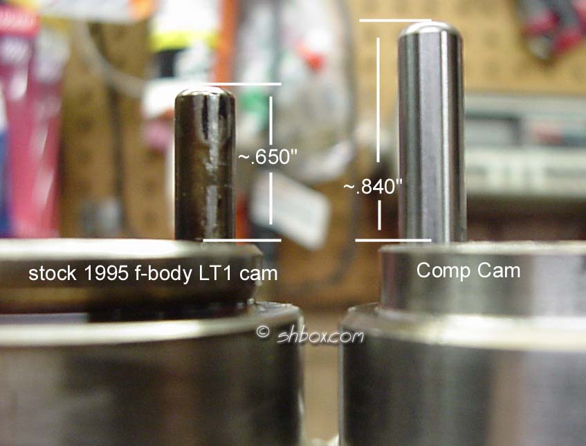
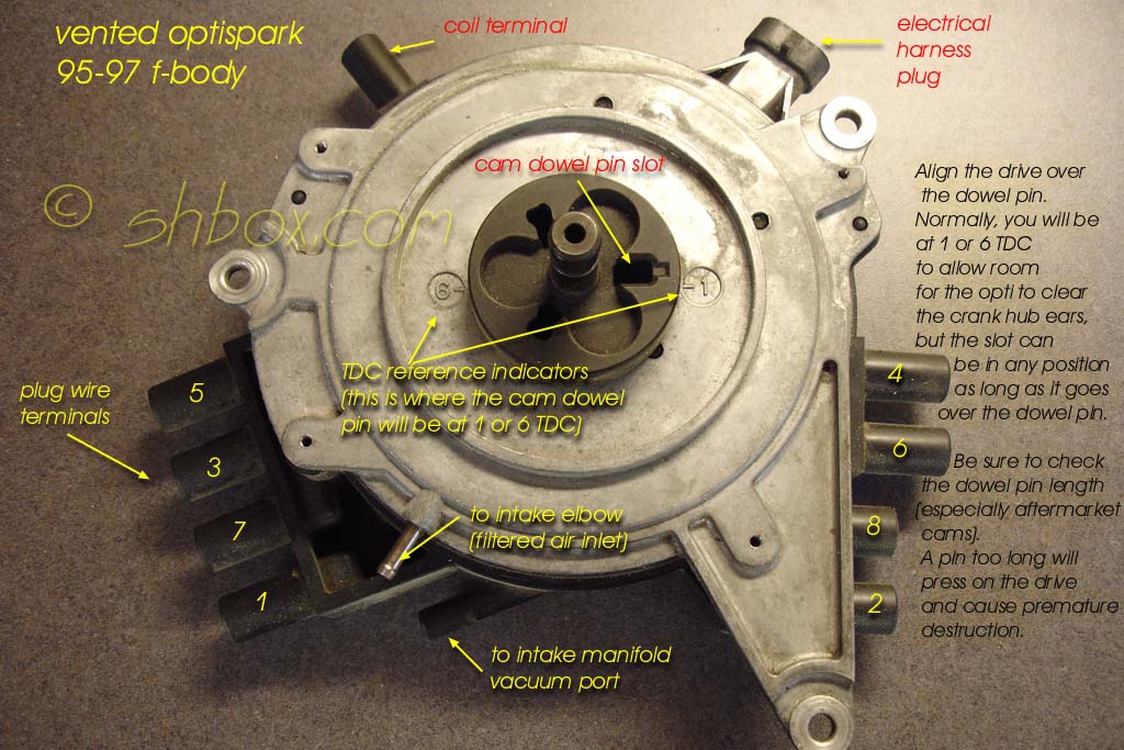
Before you install the cam, it is a good idea to check the dowel pin length. Compare the new length to the old and make any adjustments if needed. If the dowel pin is too long, it can ruin a vented optispark in a short time (non-vented optisparks aren't driven by the dowel pin). Some have said GM specs indicate that the dowel should be .620" long (protrusion from the front face of the cam) for the vented optispark. Others have said it is supposed to be .685". Mine was actually .650" and still was in no danger of bottoming out in the optispark drive (I'm thinking .685" might be the max it could be). Here you can see the difference in the Comp Cams dowel (right) to the original. The CC pin was .840". That would put pressure on the back of the optispark and destroy it in a short time. If you have any doubts about the length, use some modeling clay (even PlayDoh :-) ) to test fit the opti and check the clearance. Comp Cams advises you to check all clearances.
If you don't want to change the pin, it can be dressed down by a grinder with relative ease.
Since we are now on the install phase, you should take some time to clean up all gasket surfaces. It's a lousy job sometimes, but it will help to make your new install leak free. It's a good idea to clean up your bolts and bolt holes (use a thread chaser on holes-not a normal tap). This will help with sealing and give you accurate torque readings. Fastener torque values are listed within the text of this article and I have also compiled a complete list for the job.
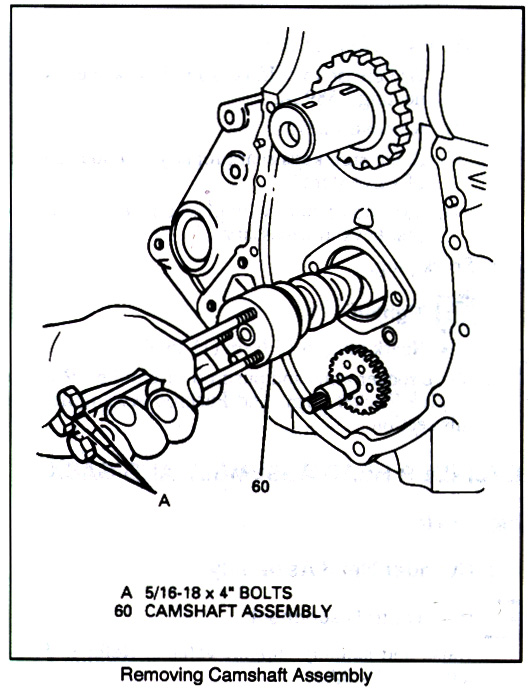
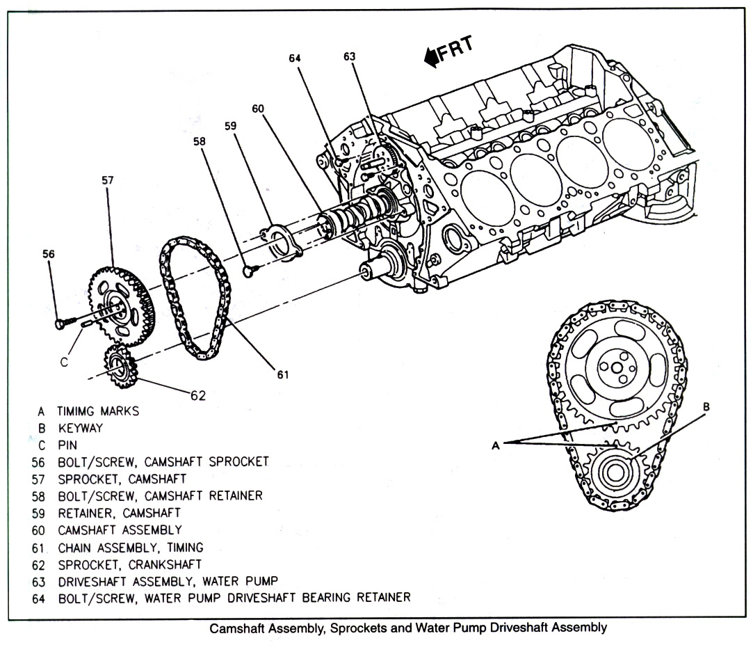
Install cam. Lubricate the camshaft journals with oil. I also chose to lube the lobes with oil as well since this is a roller cam and the lifter rollers do not skid on the lobes like they do on a flat tappet cam (use cam lube on the lobes if that makes you more comfortable or your cam manufacturer says to). I kept the gasket surfaces below the cam protected from contamination with paper towels and rags.
Rotate and support the cam as you slide it in, to protect the cam bearings from damage. Use bolts in the front of the cam or a cam holder tool to help you, if needed.
Install cam retainer (T30 Torx bolts - torque to 105 lb. in.) I also used a dab of red threadlocker on the bolts for insurance.
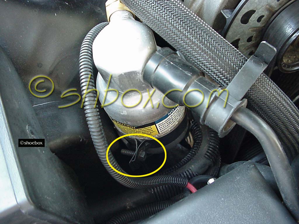
Carefully move the a/c condenser back to it's original position. Don't forget the air baffle. Put the bolt back in the receiver/dehydrator bracket.
Install oil pump drive. (1/2" bolt- torque to 13 lb. ft.)
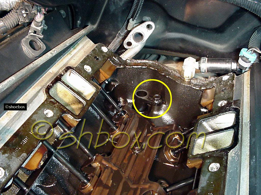
Install lifters. I installed new lifters with my new cam. New lifters often have a sticky protectant on them to keep rust away while packaged. A bath in some solvent and good drying should take care of it. You dont' want that gummy stuff keeping your lifters from oiling up. I submerged each in oil to lubricate them and to get as much oil in them as possible. The oil holes in the lifters can face either front or back.
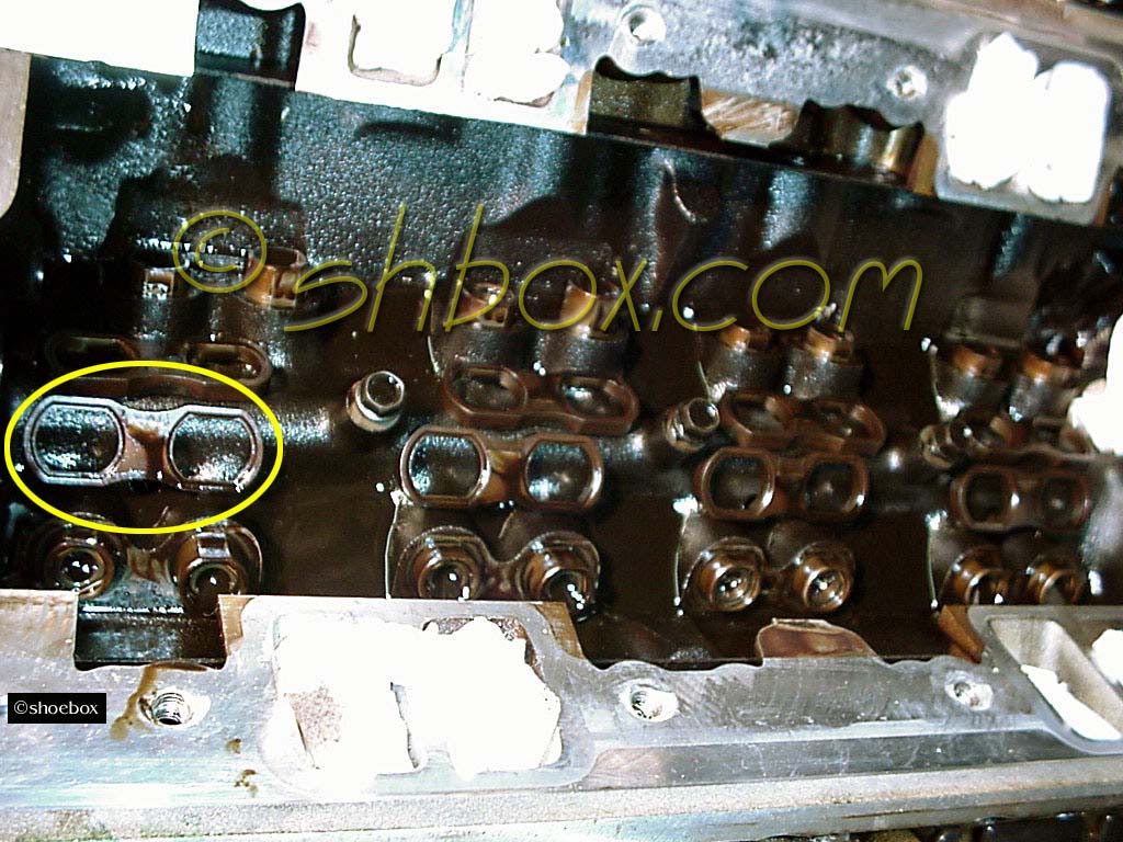
Install lifter guides.
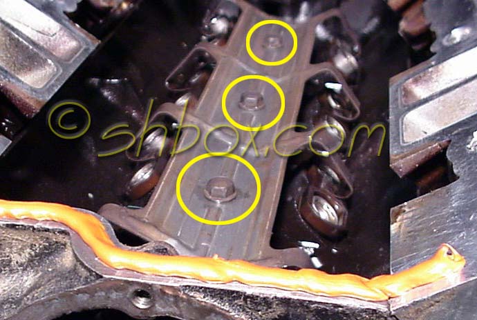
Install lifter guide retainer (spider). Notch in spider goes toward the front. (three 1/2" bolts - torque to 18 lb. ft.)
If you want, go ahead and slip your pushrods back in, so you can see that they sit in the lifters properly. If you are comfortable with putting them in later after the intake manifold is on, that's ok, too.
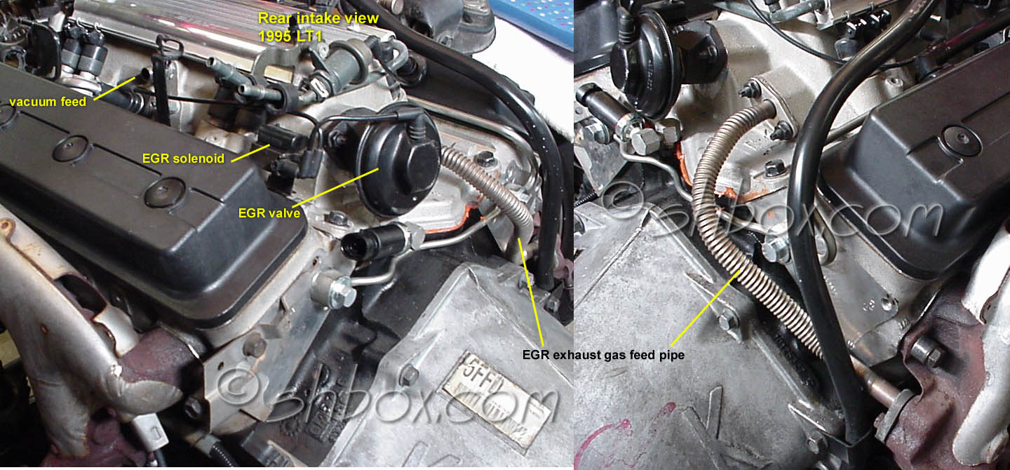
Install EGR valve if not previously installed. (two 1/2" nuts - torque to 18 lb. ft.) It is much easier to install this before putting the intake on.
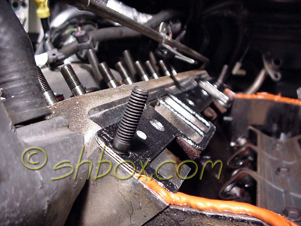
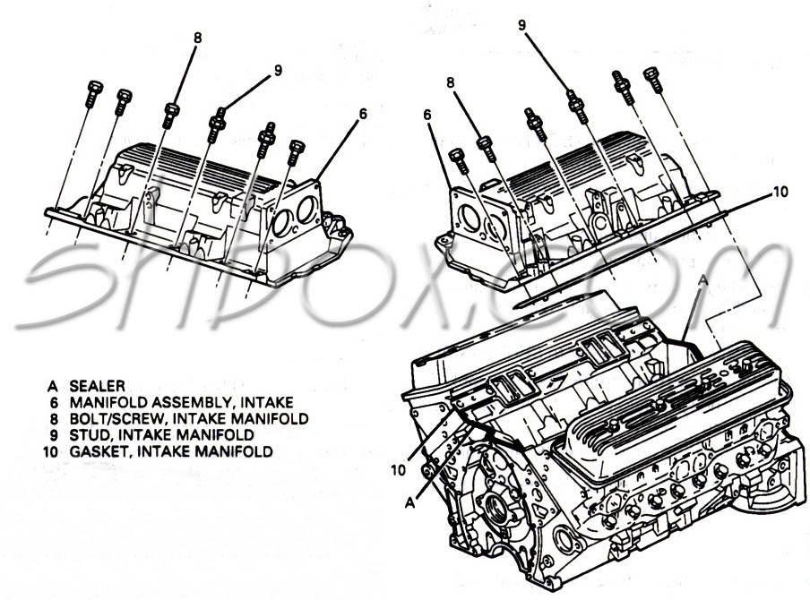
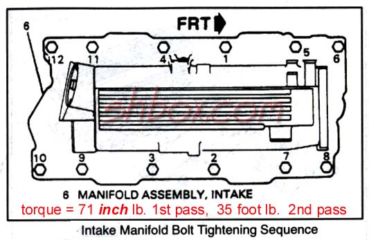
Install intake manifold. Use of locating studs or dowels (3/8-16 thread) on one side will allow you to set the manifold on without wallowing it around and ruining the RTV seal in the middle. (9/16 bolts/studs with thread sealant on them- torque to 71 lb. in. first pass and 35 lb. ft. second pass. Follow the proper sequence for tightening)
It is generally recommended that you let the intake sit 24 hrs for the RTV to cure before you fire it up. That is one reason I have installing the intake first during reassembly. It can be curing while you put on the rest of the stuff. Some people don't let it sit that long and have been ok.
Connect EGR pipe to back of manifold (two-1/2" nuts - torque to 18 lb. ft.)
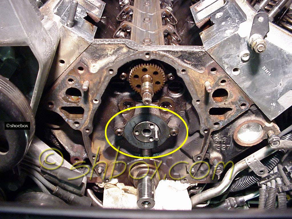
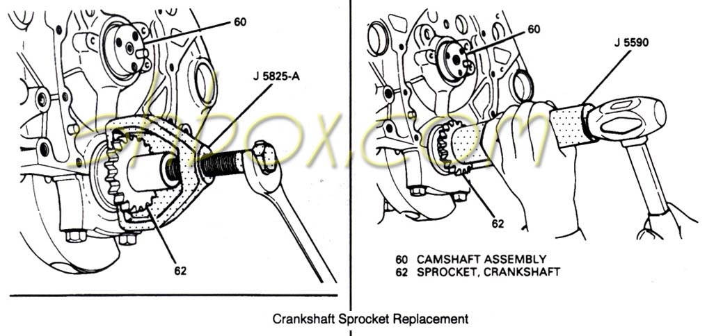
Install crank sprocket. Use a suitable tool for putting the sprocket on. Make sure your "dot" is facing out and line up the crank key. The sprocket should be flush with the machined shoulder on the crank when fully on. If you have a hub install tool, you could use a piece of pipe as a spacer to crank the sprocket into place.
Install cam sprocket and timing chain. (1/2" bolts - torque to 18 lb. ft. I used some red threadlocker on them) Line up the dots on the timing gears. 12 o'clock for the crank gear and 6 o'clock for the cam gear. This will put the cam dowel at 3 o'clock and #6 TDC.
Assemble chain onto the cam sprocket with the chain slack dangling below. Holding the sprocket with the dot on the bottom, lower the chain under the crank sprocket and then pull up to engage the teeth and remove the chain slack. Slip the cam sprocket onto the cam dowel. You may have to turn the cam just a little to get enough slack to get it on. After you get the the sprocket on the dowel, insert one bolt through the sprocket into the cam. Check the alignment of the dots and redo the procedure if needed.
If you would like to view the relationship between the cam and crank (including gear dots and dowel pin) as they go through the firing order, click here.
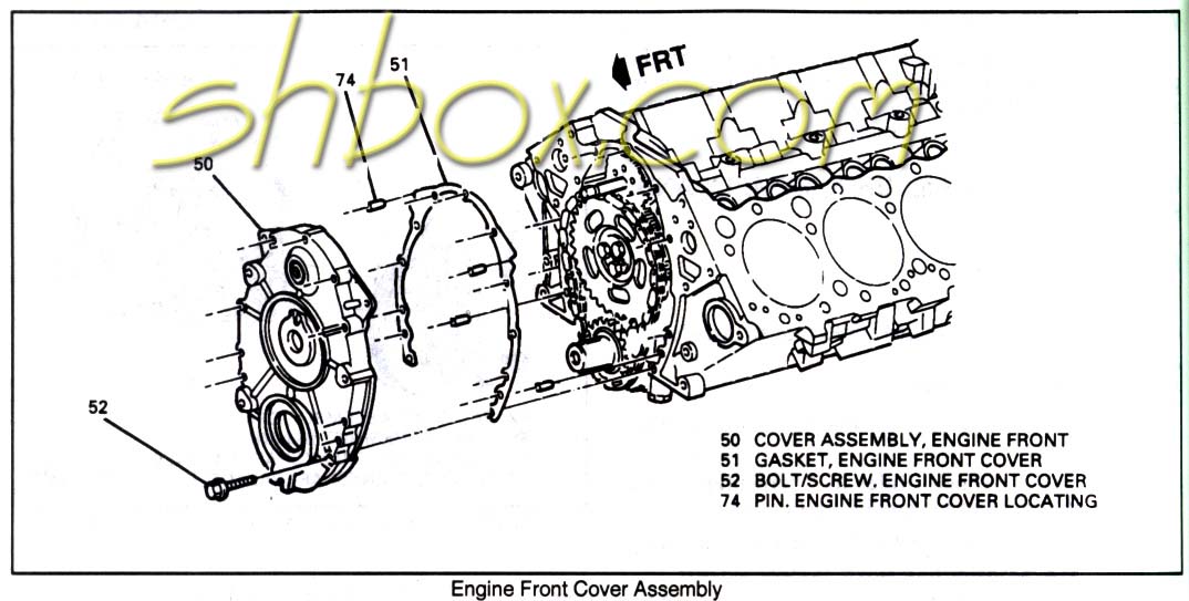
Install front cover. (3/8" bolts - torque to 100 lb. in.) Clean the area where the oil pan seal is and carefully guide the seal into the timing cover as you put it on. Use of some RTV sealant may be desired to help keep away any leaks (I used some).
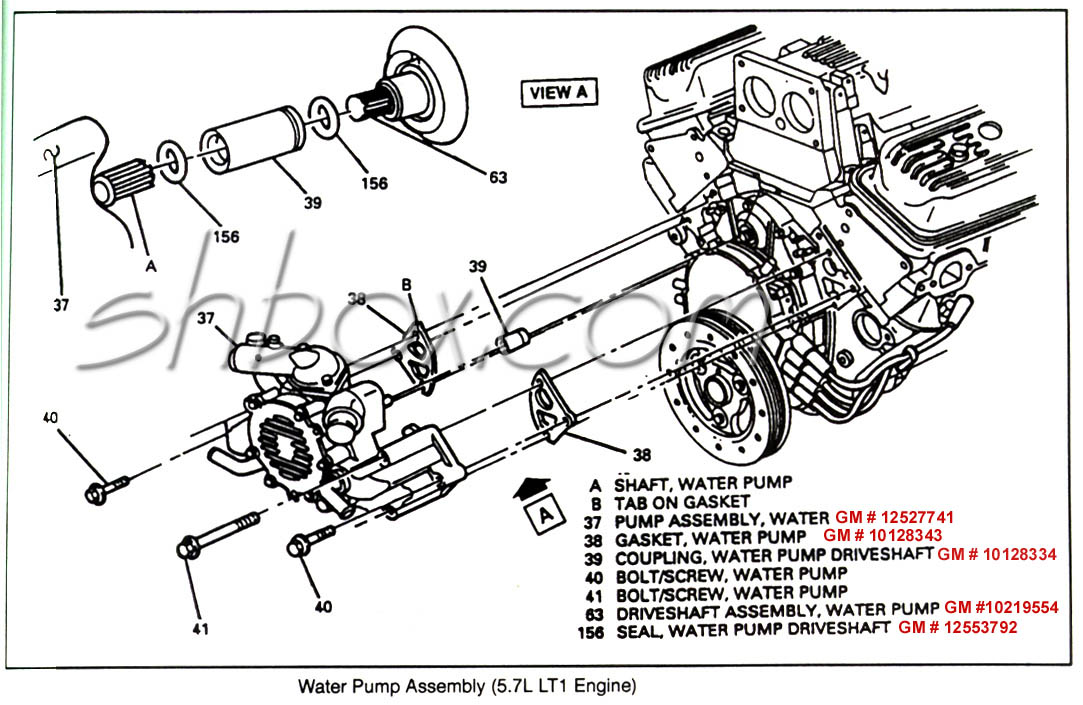
If you are replacing the seals in the front cover (and it is a good idea), leave the water pump driveshaft seal off and install it after the cover has been installed. It is very easy to rip the seal on the water pump drive, so some extra care needs to be taken.
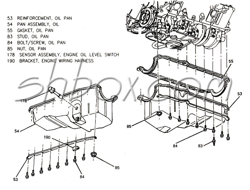
Re-attach oil pan. (1/2" corner bolts - torque to 15 lb. ft., 3/8" rail bolts - torque to 106 lb. in.)
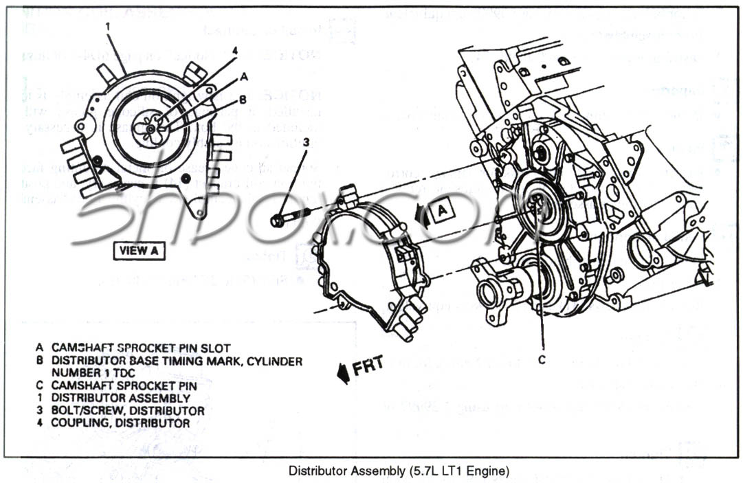
Install optispark. (3/8 bolts - torque to 106 lb. in.) Use new o-rings on the drive mechanism if yours are missing or brittle. Be sure to orient the drive correctly for proper timing. If you put the sprocket dots together, you are at #6 TDC and the cam dowel is in the 3 o'clock position. On the back of the opti, point the special slot on the opti drive to the "6". Line up the mounting ears of the opti with the bolt holes on the front cover. Don't disturb the drive position and slide the opti on until it fits flush. If it does not fit flush, remove it, check the alignment and try again. Did you forget to check the dowel pin length on your new cam?
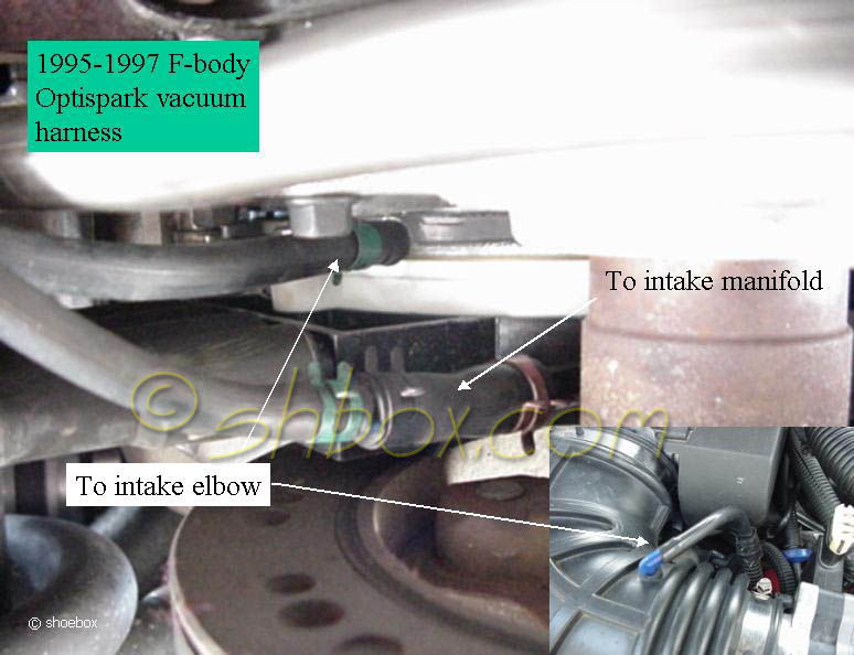
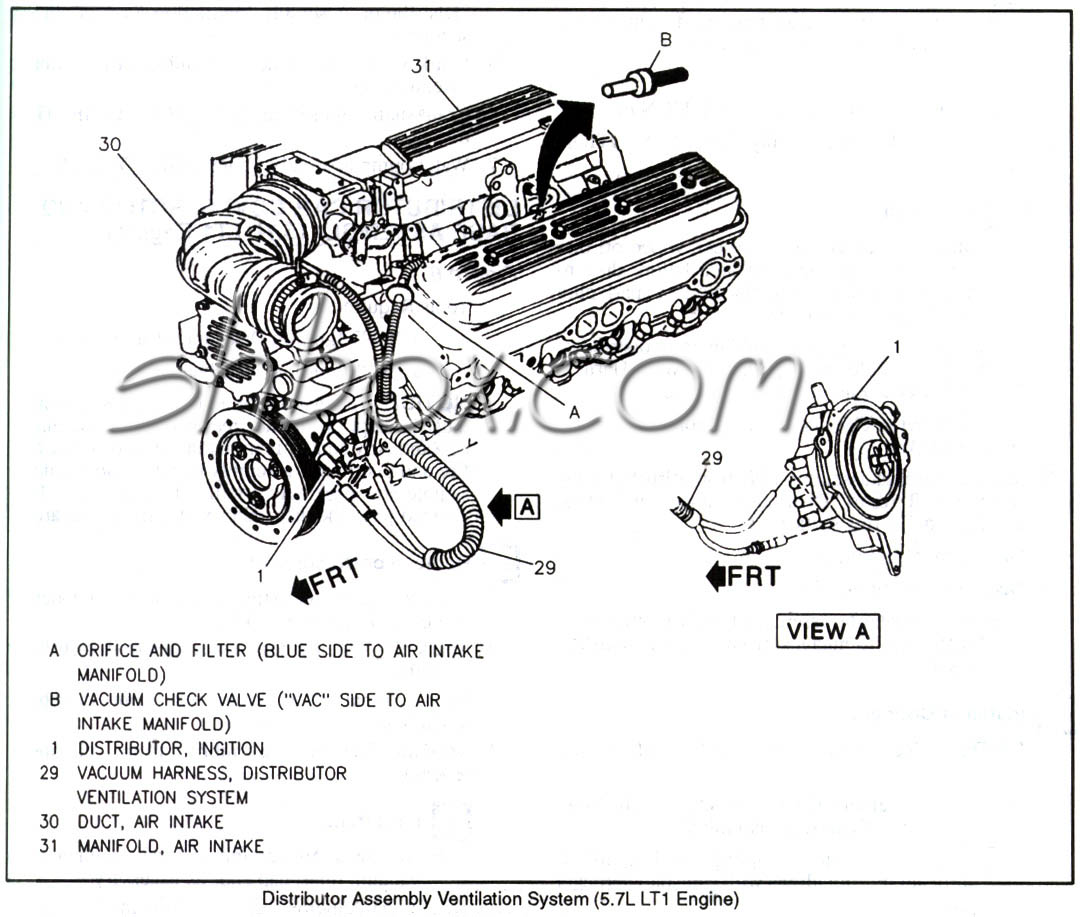
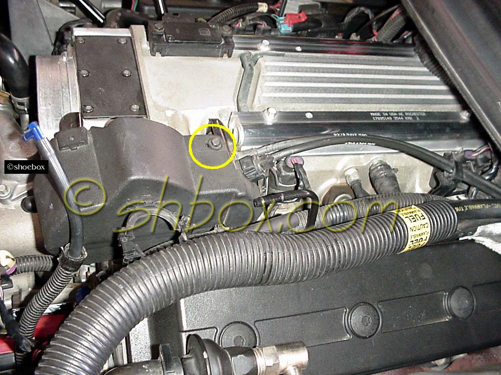
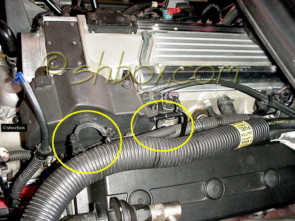
Install the optispark vent/vacuum hoses.
Optispark vent diagram
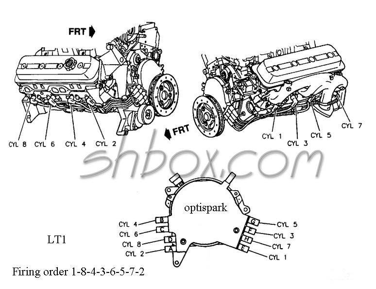
Connect spark plug wires to optispark. The cylinder numbers are embossed by the plug wire towers on the opti.
Install water pump. (9/16 bolts with thread sealant - torque to 30 lb. ft.) Use new o-rings in the drive shaft grooves and put a dab of lubricating grease on the splines. The o-rings help keep the grease in and dirt out. The drive coupler is installed with the groove toward the engine (did you inspect the coupler and drive for excess wear?). New o-rings can cause it to be a little harder to compress back on.
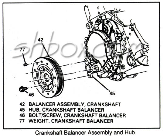
Install crankshaft hub. (5/8' bolt - torque to 75 lb. ft.) Use the correct installation tool and not the hub bolt to pull the hub on (or make your own install tool from high grade threaded rod, thrust washers and nuts).
Install AIR pump bracket. (9/16 bolts - torque to 30 lb. ft.)
Install AIR pump. (three 10mm bolts - torque to 50 lb. in.) Don't forget the one on the back of the bracket that fastens the AIR pipe and wire loom.
Install crankshaft pulley. (5/8" bolts - torque to 63 lb. ft.) Note that the spokes of the pulley are not symmetrical and that the bolts will only line up one way. The arrow on the pulley will line up with the line that is marked on the hub (you probably have this at the 12 o'clock position).
Install pushrods (if you haven't already), rocker arms and set valve lash/preload.
Install valve covers. (3/8" bolts - torque to 106 lb. in.)
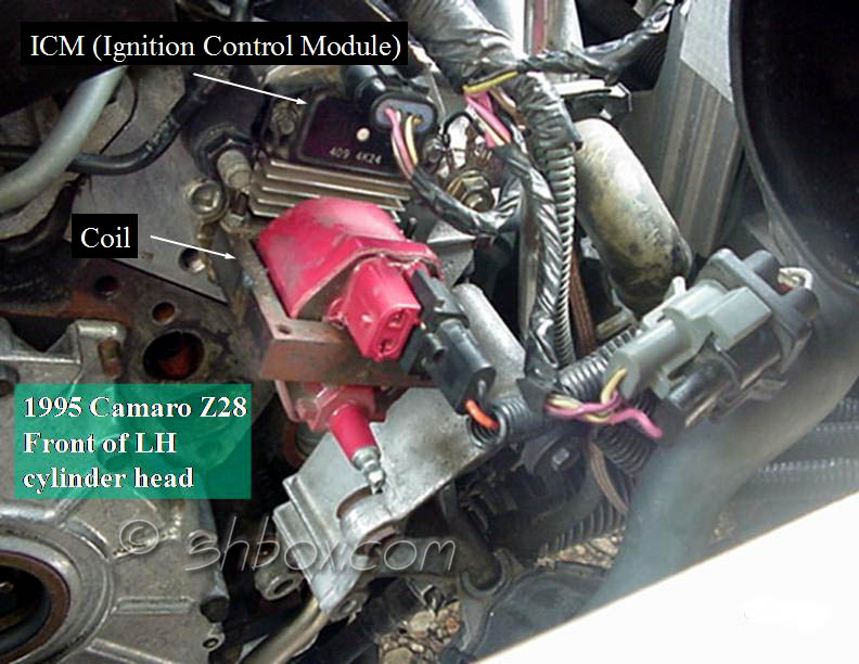
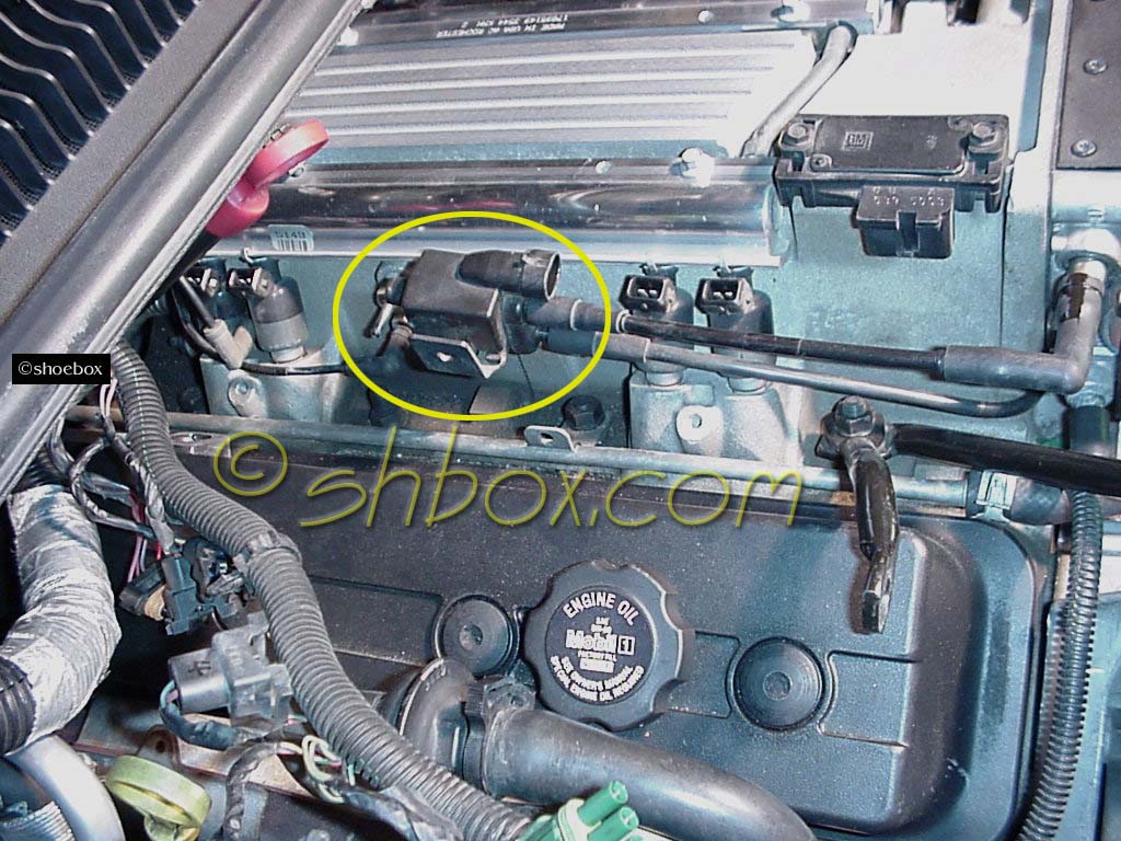
Install and connect coil assembly if you removed it. (torque studs and nuts to 18 lb. ft.)
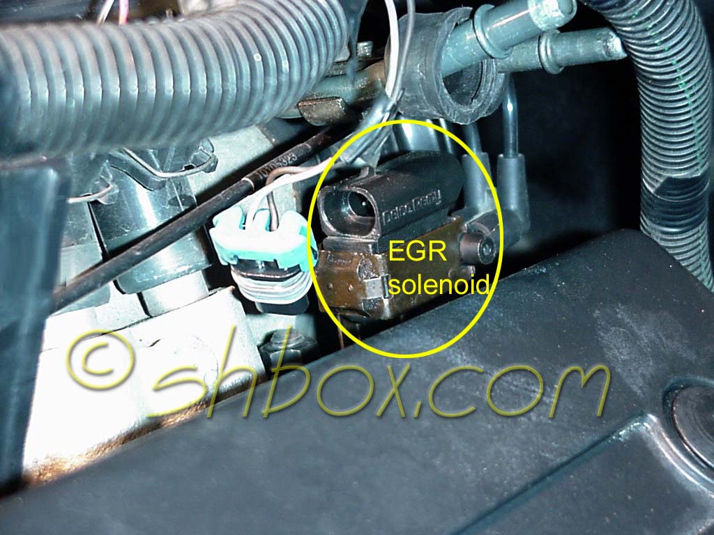
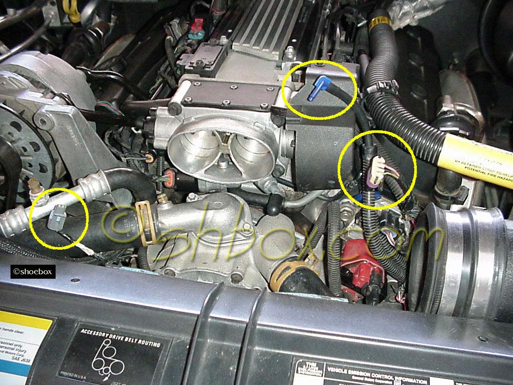
Install EVAP and EGR solenoids, vacuum lines, etc.
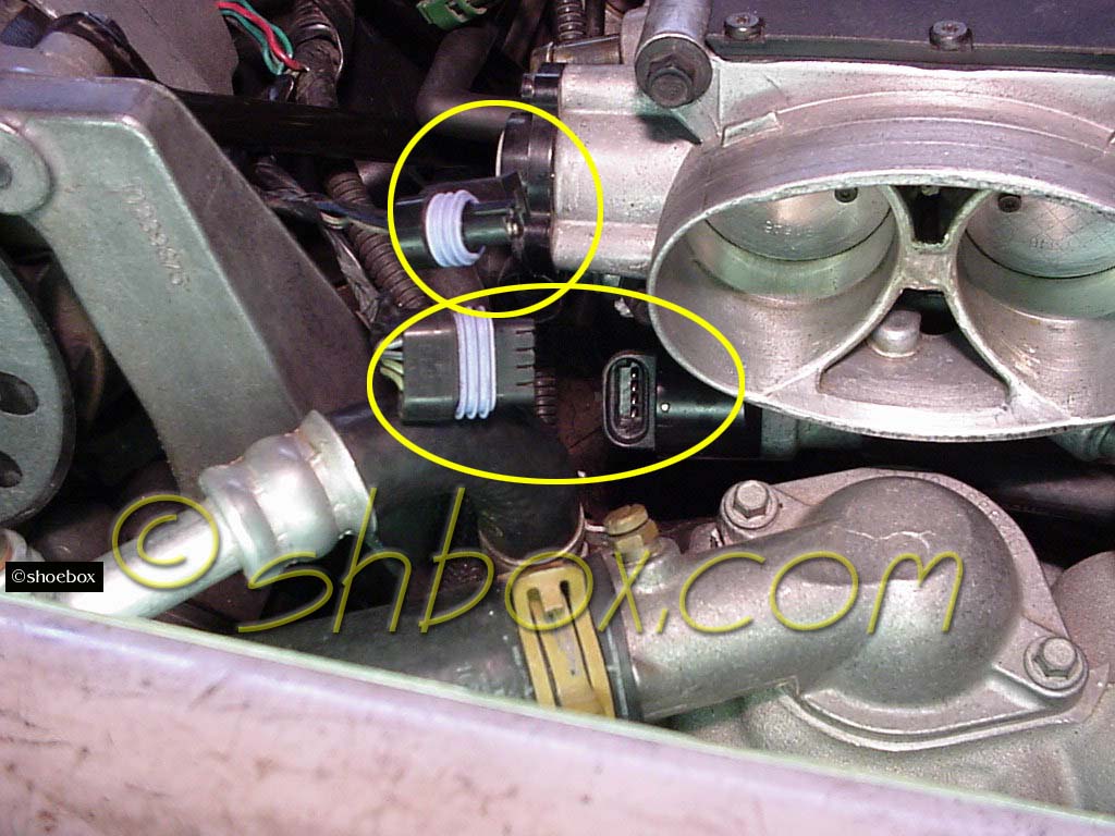
Install throttle body (10mm bolts - torque to 18 lb. ft.) and reconnect accelerator and cruise control cables.
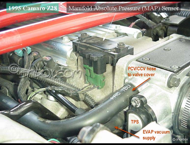
Reconnect electrical connections: injectors, EVAP and EGR solenoids, water pump temp sensor, optispark, IAC, TPS, MAP.
Install radiator and radiator cover (three 8mm bolts - torque to 106 lb. in.), reconnect low coolant sensor, all hoses and transmission coolant lines if applicable.
Install fan assembly and connect fans.
Attach accelerator cable bracket cover (7 mm bolt )
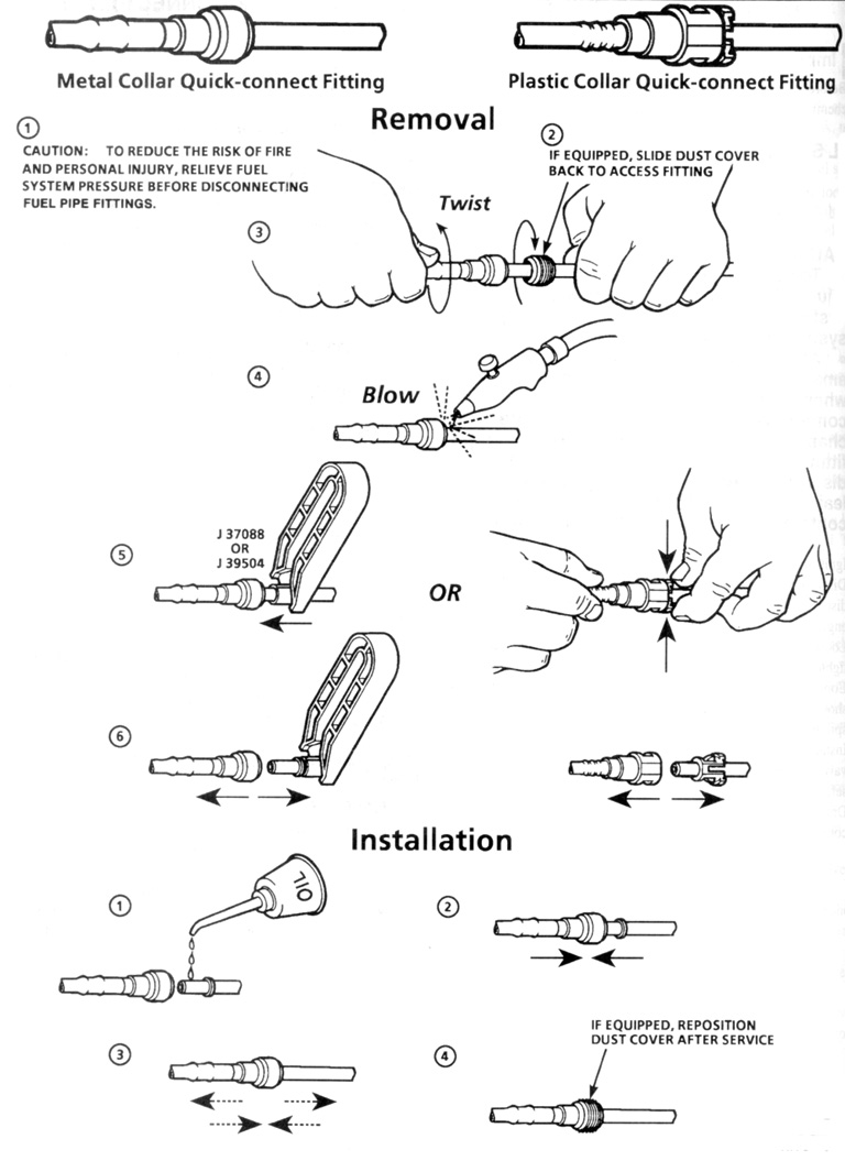
Connect the fuel rail lines. They should just push on. Slide the protective boot over the connectors when done.
Connect the EVAP hose and attach fuel rail clips.
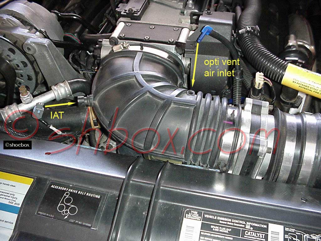
Install intake elbow, MAF and any other air intake parts removed. Plug in the MAF, IAT and optispark vent.
Install/connect alternator and serpentine belt. Alternator to accessory bracket bolts and the upper, back brace bolt, torque to 37 lb. ft. Torque upper brace mounting nut at intake manifold to 24 lb. ft. and the lower, back brace bolt to 18 lb. ft.
Refill the cooling system.
Reconnect the battery only after everything else has been connected. (5/16" bolt - torque to 11 lb. ft.)
Follow your cam manufacturer's recommendation on engine rpm after cam install. Most like to see the engine kept at about 2000 rpm, initially. Even though this is not a flat tappet cam, the higher rpm is necessary to provide oil splash on the cam lobes, as this is the only way they get lubricated.
After engine has been run through a few heat and cool cycles, check the torque on the intake manifold bolts.
Don't forget to put the air dam back on before you road test. (8mm bolts - torque to 106 lb. in.)
edited 9/23/2012

Use any info from this site at your own risk.
You may link to these pages/images but not copy for the purpose of
re-hosting,
reselling or publishing without expressed permission.
Picture or text links to auction sites (ex. Ebay) are forbidden.
All rights reserved by shbox.com.