|
Getting Started
Disconnecting the negative battery cable will keep you from inadvertently shorting anything out when removing connectors under the dash. Begin with steering wheel pointed straight ahead and ignition LOCKED. Make sure you know your security code for your radio, if appropriate. Auto transmission cars should be in PARK.
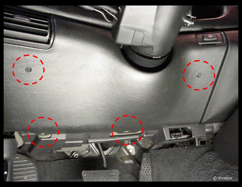
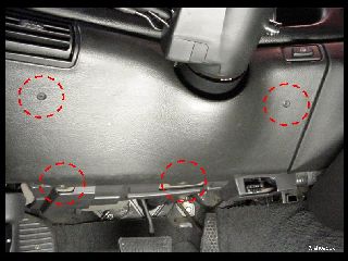
First, you will need to remove the knee bolster under the steering wheel. There are two phillips head screws on the upper part and two 7mm hex head screws underneath. Fishing the bolster out can be a little tricky because of the rear defogger switch and the way the panel fits around the steering column.
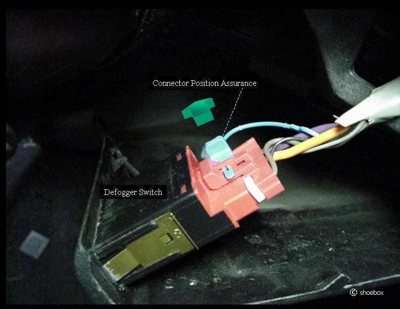
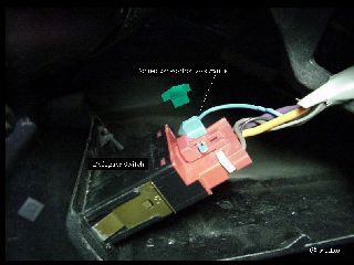
Once you get the panel pulled out a little, you then have to wrestle with the defogger connector (it would help if you had a couple more hands!). Try to pull some of the slack in the wiring through the switch hole.
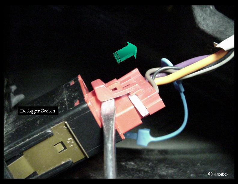
Remove the Connector Position Assurance (CPA) retainer (I bet you never knew that little plastic pin that keeps a connector from coming apart was called that ;-) ) and then release the connector (it is a tough one!). If you don't have a defogger, you have it easy!
|
|
|
Disconnecting/Removing
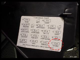
I recommend disabling the air bags at this point, if you did not disconnect the battery (pull the fuse anyway-you can never be too sure!).
Pull the air bag fuse first. NOTE: If your working environment is such where static electricity is a concern, ground yourself by grabbing a piece of metal on the car before working with the air bag wires.
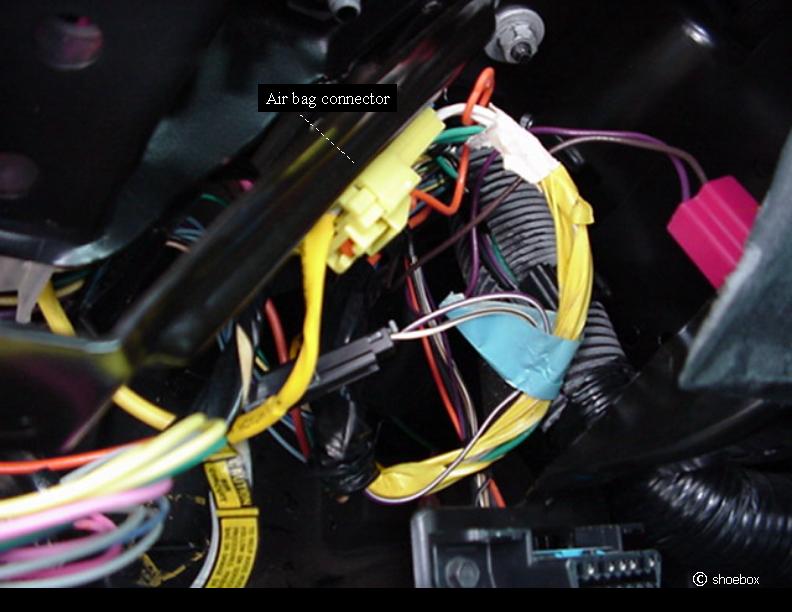
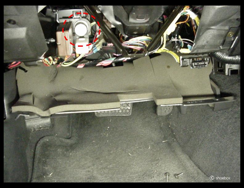
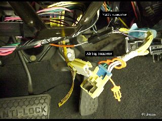
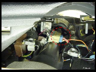
Next, find the yellow, two wire connector coming from the steering column. It may be clipped to the knee bolster deflector ("V" looking bracket).
Remove the CPA and unplug the connector.
Note the position of the deflector, because it is not symmetrical. Remove two 10mm nuts and place the deflector aside.
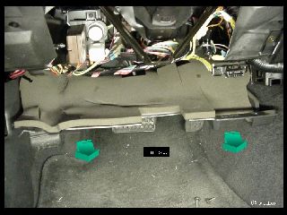
There is also an insulator panel under the dash. There are a couple of "Christmas tree" fasteners at the front corners. The back of it inserts into slots in the firewall cover. Remove the fasteners and pull the panel straight out.
Note the various connectors on wires coming from the column. You will have to disconnect them so the column can come out.
|

|
|
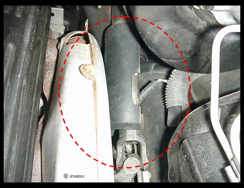
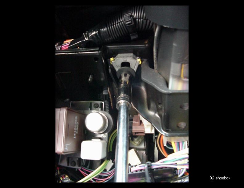
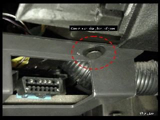
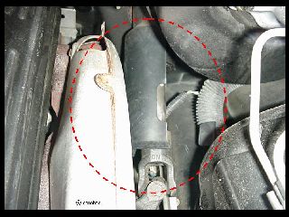
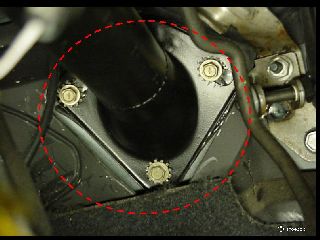
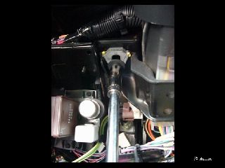
Open the hood and locate the upper connection of the steering column shaft. There should be a plastic shield over the joint and bolt. It merely unsnaps off the column.
Verify again, that you have the wheels pointed straight ahead and the steering wheel is LOCKED.
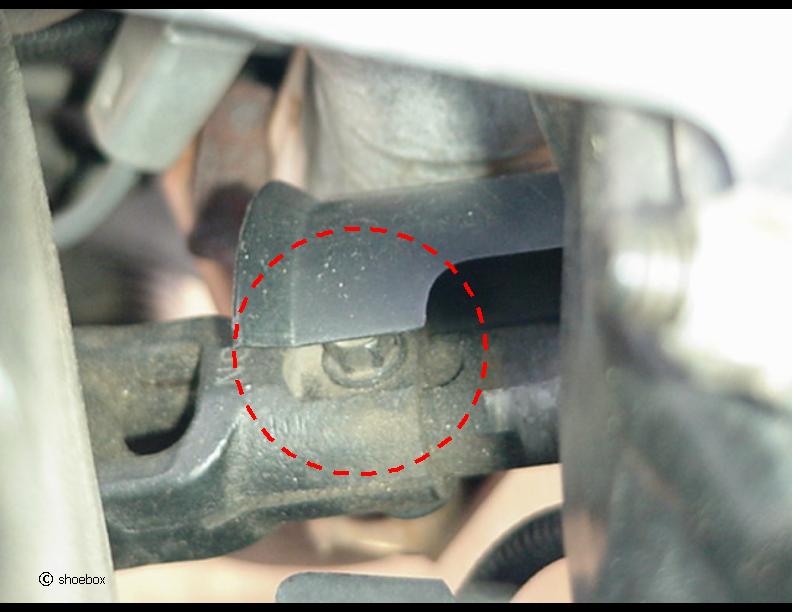
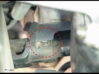
Remove the 11mm through bolt. Adding a reference mark on the inner part of the shaft can aid in telling you how far to slide the shaft back in during reassembly.
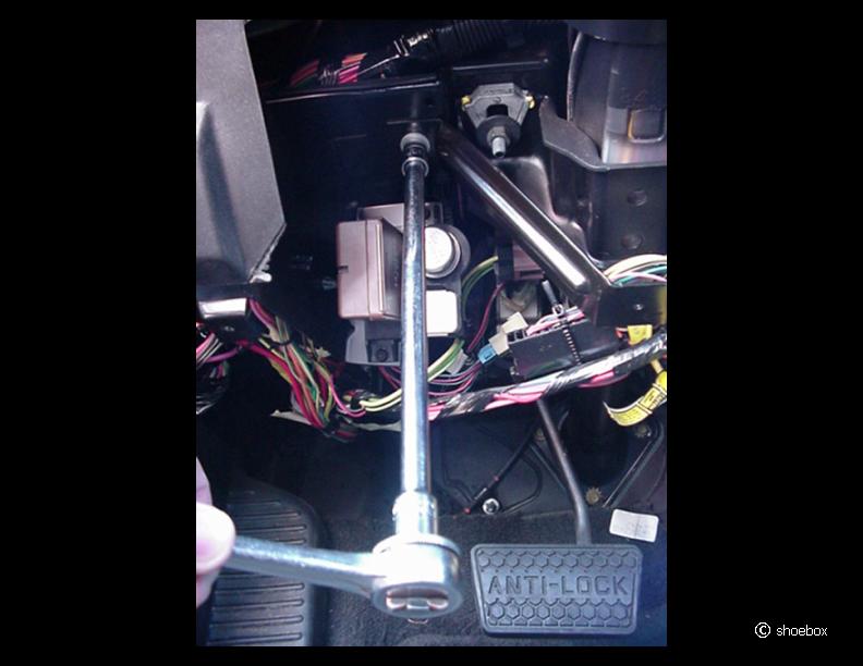
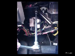
Remove the three 10mm bolts at the base of the steering column flange at the firewall. These are long, fine thread bolts. It is much easier if you put several extensions together, so you don't have to ratchet under the dash.
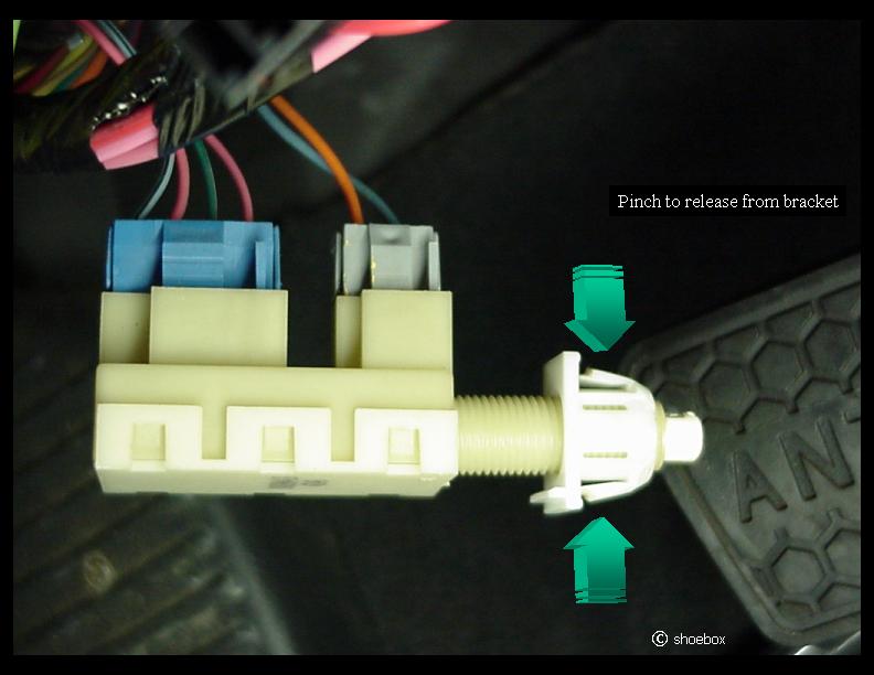
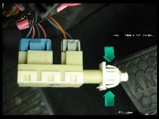
When the column is lowered, it will want to angle to the left and the dimmer switch may cause inerference. Because of this, it is a good idea to remove the lower brake light switch so it does not get in the way and get broken.
Depress the brake pedal and "pinch" the tabs on the back side of the bracket and pull the switch out.
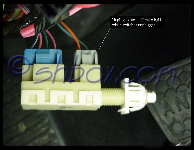
If you don't want your brake lights to be ON all the time you are working on this, unplug the gray connector from the switch to extinguish them.
I also removed the hazard flasher for additional room.
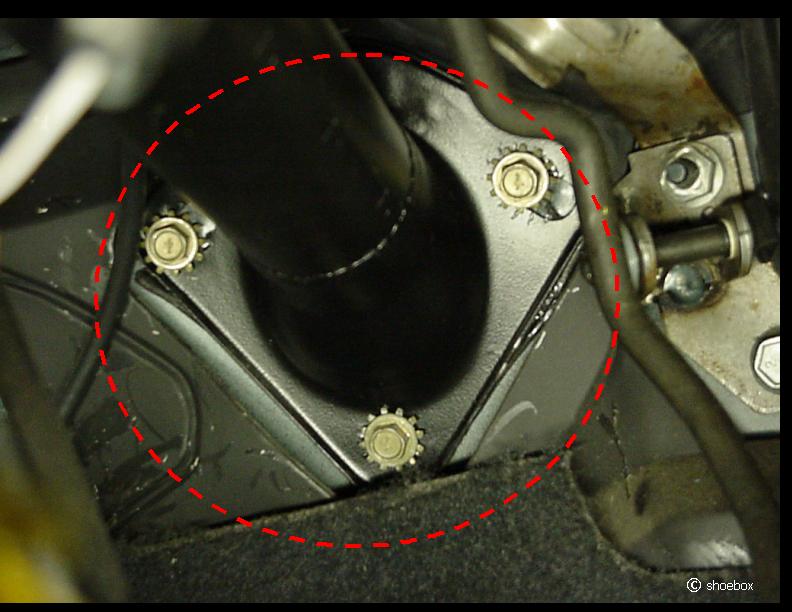
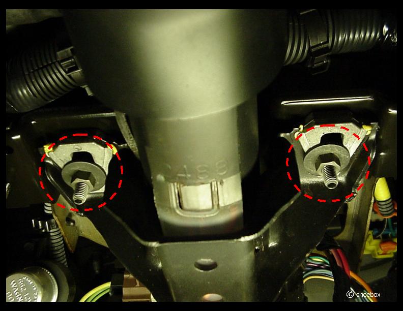
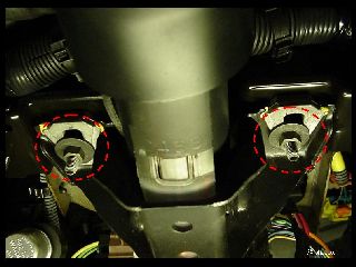
There are two 13mm nuts securing the column to the dashboard structure. Use a deep socket to remove them (you could also use a wrench to get them loose and then spin them off while supporting the weight of the column). The column's weight will pull it down as the nuts are removed, so give it some support while removing the nuts.
Watch for any interference as you lower the column. If you need to adjust something, merely push the column back up and temporarily spin one of the nuts on a little.
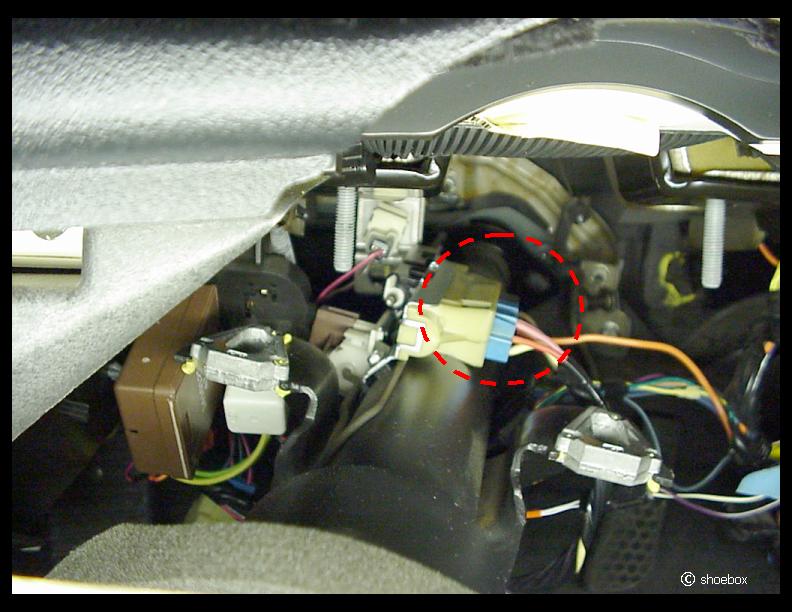
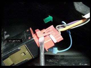
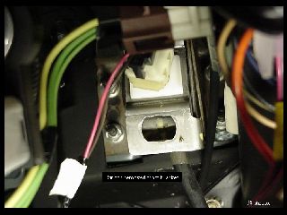
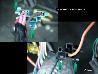
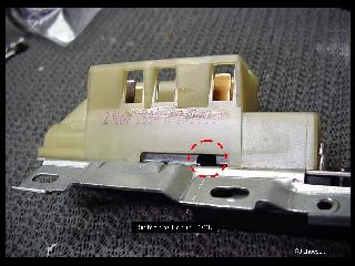
Once you have the column lowered, you will be able to reach the two connectors on the ignition switch. There was a black and a blue one on mine.
You must remove the black connector before the blue one will come out.
Pinch the levers on the connectors to release them and pull connectors out.
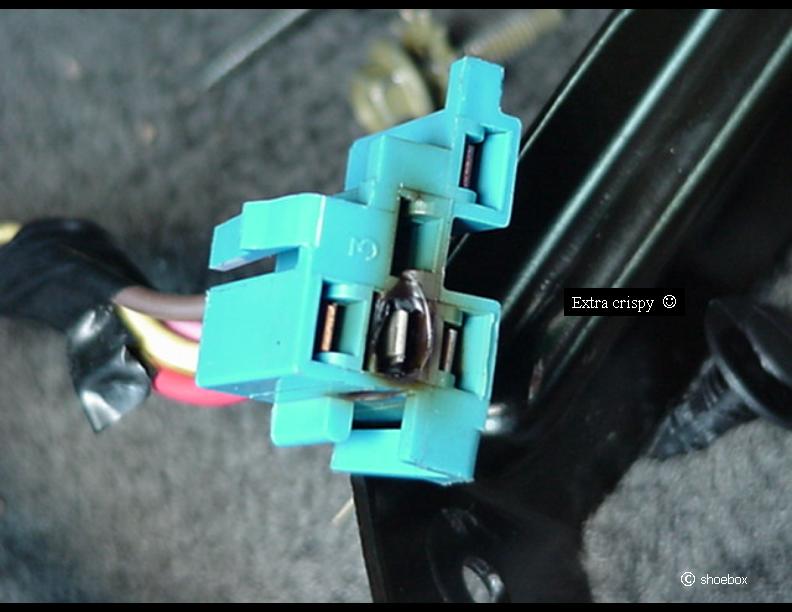
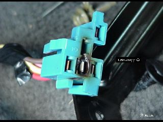
It is fairly typical to find some heat damage to this connector. If the damage is severe, a replacement pig tail is ACDelco part # PT289 (PT290 for the black connector). I would recommend heat shrink tubing and solder to splice in a new connector. If you can manage it, you could release and re-insert the old, undamaged terminals into the new connector, so you would not have to splice much.
If you don't need to replace the connector, at least make sure that the metal contacts have good "spring" to them and will make proper contact to the switch lugs. Heat from the connection has a way of relaxing the metal and making contact poor. Heat causes poor contact, poor contact causes more heat...you see where this is going, right?
Verify your auto transmission selector is in PARK (key still in LOCK). Remove the automatic transmission park/lock cable from ignition switch, by grasping it near the back of the switch and pulling straight out, unsnapping cable from switch. It can be a bit stubborn, but should come out with enough determination. You manual transmission folks don't have to worry about this step.
|


|
|
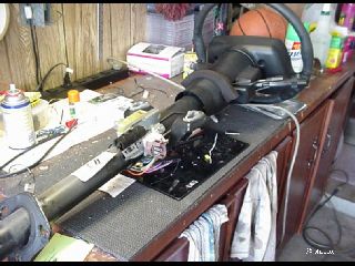
Pulling The Column
Make sure you have released all connections from the column (don't forget the dimmer).
Support the upper and lower part of the column and slide it out of the intermediate shaft that is on the other side of the firewall. Don't go nuts if it won't release from the intermediate shaft. Support or set the column down and try giving the shaft connection a few taps on the side with a hammer to break any corrosion.
NOTE: When the steering column is removed from the vehicle, it is extremely susceptible to damage. Dropping the column assembly on its end could collapse the steering shaft assembly or loosen plastic injections that keep the column assembly rigid. Be careful with it.
DO NOT turn/spin the steering wheel. Keep the wheel locked. The wheel must remain centered as it came out, to protect the SIR (air bag) coil leads from damage.
|
Replacing The Switch
You now have plenty of room to replace the switch!
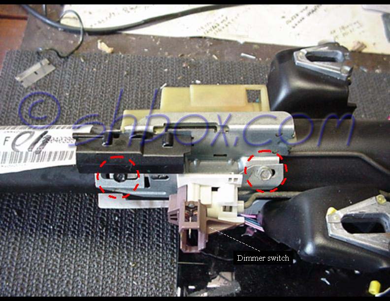
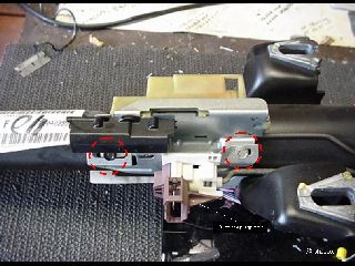
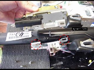
The dimmer and ignition switches are held on by the same 8mm screws.
I marked the location of the screws to the bracket of the dimmer, so that I could put it back on in the same place and not upset the dimmer switch adjustment.
Once the screws are removed, pull the ignition switch up and away from the column to separate it from the actuator rod.
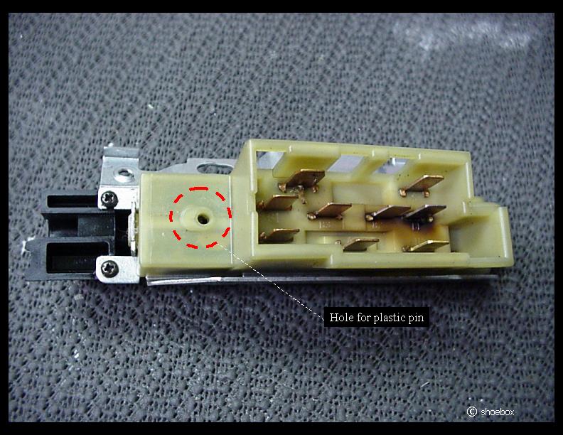
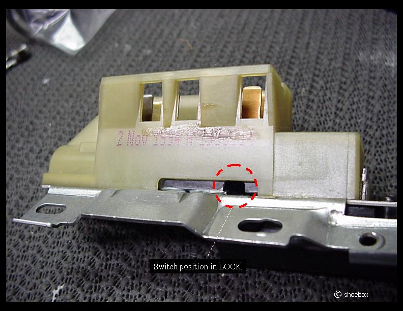
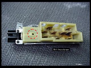
When you get a new switch, it will probably have a plastic pin in it, holding it in the LOCK position. Make sure you remove this pin before putting the column back in the car.
Your column should already be in the lock position, so just line up the hole in the new switch with the rod and set it on. Reattach the dimmer back on top, using the position markings you made earlier.
Remove the plastic pin in the switch and test the key to see if it seems to operate normally in all positions. DO NOT turn the steering wheel while you are doing this. You want to keep the position like it was when it came out.
|
|
Putting It Back Together
Install/Reconnect the following:
- Align the column to the intermediate shaft, slide it in, thread one or both of the column support nuts on to hold the column up.
- Intermediate shaft bolt. Torque to 35 lb. ft.
- (If you want to test the switch before tightening everything back up, make all connectons and give it a try.)
- Auto transmission park/lock cable by inserting cable until it "snaps in" (lower column temporarily if you need room). Remember, it can be a little stubborn.
- Column flange to firewall bolts. Torque to 14 lb. ft.
- Column support nuts. Torque to 18 lb. ft.
- All electrical plugs
- Brake light switch and any connector removed from it, hazard flasher
- Air bag fuse
- Battery cable (this is a good time to test switch function if you have not already)
- Knee bolster deflector. Torque to 17 lb. in.
- Sound insulation panel
- Knee bolster and connect defogger switch (if applicable)
|
Feel free to
email me with any comments or suggestions.
You may link to these pages/images but not copy for the purpose of
re-hosting,
reselling or publishing without expressed permission.
Picture or text links to auction sites (ex. Ebay) are forbidden.
All rights reserved by shbox.com.